W
Point
A,
'
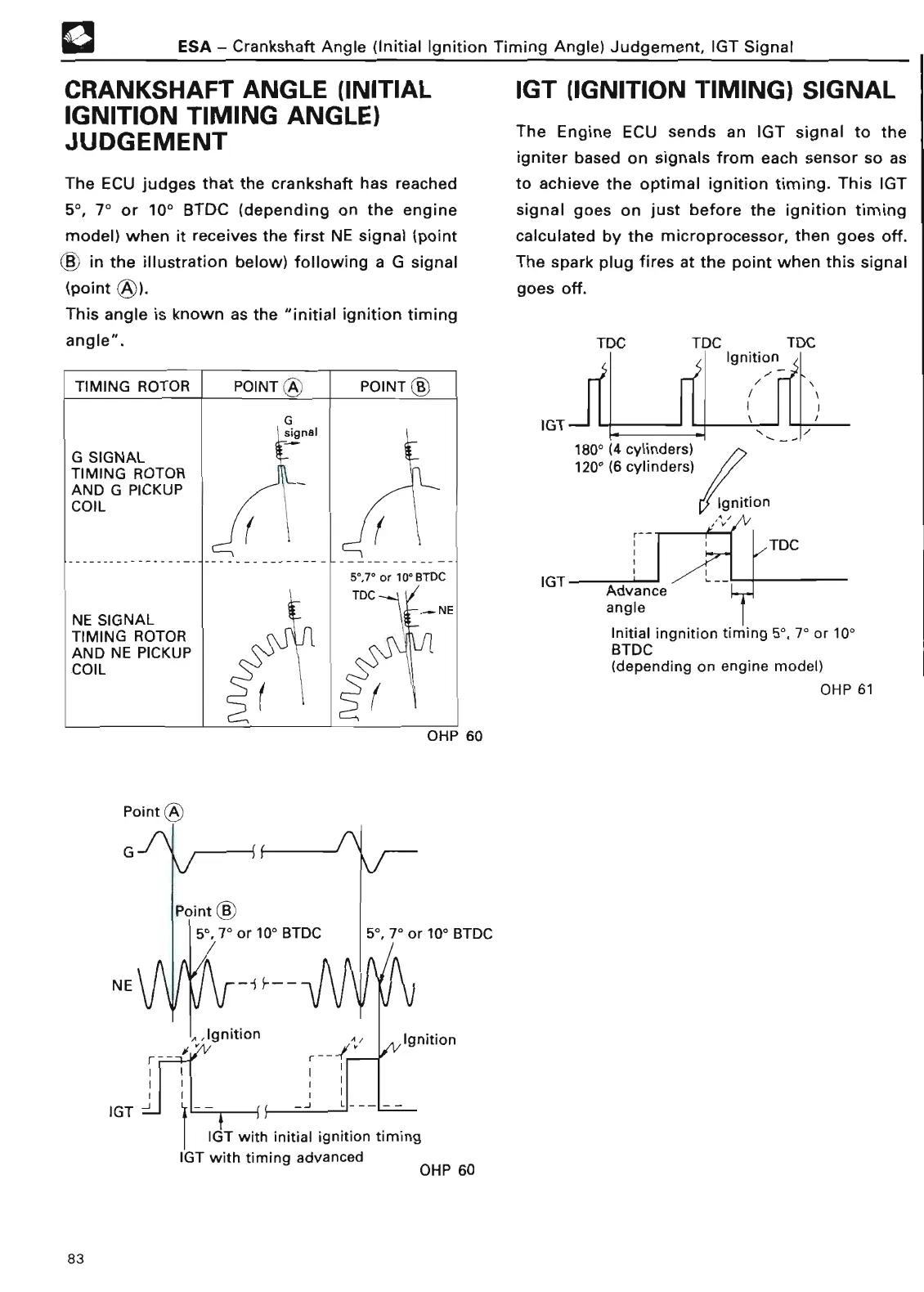
CRANKSHAFT ANGLE
(INITIAL
IGNITION TIMING ANGLE)
JUDGEMEN
T
The ECU judges that the crankshaft has reached
5°, 7° or 10° BTDC
(
depending on the engine
model) when it receives the first NE signal (point
i
B) in the illustration below) following a G signal
(poin
t
This angle is known as the "initial ignition timing
angle"
.
TIMING ROTOR
POINT
A
.
POINT B
'
G
signa
l
G SIGNA
L
TIMING ROTO
R
AND G PICKU
P
COI
L
-------------------
-----
5',7' or 10° BTD
C
TDC
-
.
4
NE SIGNAL
-N
E
TIMING ROTO
R
AND NE PICKUP
l
COIL
OHP 6
0
Point
(
B
;
)
NE
ESA - Crankshaft
Angle (
Initial Ignition
Timing Angle) Judgement, IGT Signa
l
5
0
, 7° or
100
BTD
C
,, ,Ignitio
n
r
A ,
i
I
-J
IGT (IGNITION TIMING) SIGNAL
IGT
~
-J `---
~
IGT with
initial ignition timing
IGT with timing advanced
OHP 60
The Engine ECU sends an IGT signal to the
igniter based on signals from each sensor so as
to achieve the optimal ignition timing
.
This IGT
signal goes on just before the ignition timing
calculated by the microprocessor, then goes off
.
The spark plug fires at the point when this signal
goes off
.
TDC TDC TDC
r~
Ignition
-r-
k
i
IGTJ
~
180°
(
4 cylinders)
120° (6 cylinders)
Ignition
~-
f
V
TD
C
IGT
Advance
angle
T
Initial ingnition timing 5°,
7° or 10°
BTD
C
(depending on engine model)
OHP 6
1
83