IGNITION
CIRCUITRY
ESA - Ignition
Circuitr
y
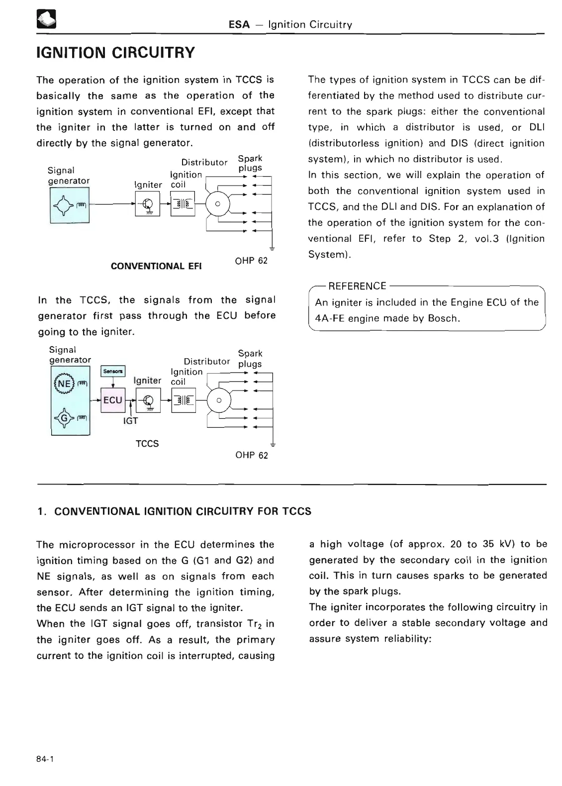
The operation of the ignition system
in TCCS is The types of ignition system in TCCS can be dif-
basically the same as the operation of the ferentiated
by the method
used to distribute cur-
ignition system in conventional EFI, except that rent to the spark plugs
: either the conventional
the igniter in the latter is turned on and off
type, in which
a distributor is used, or DLI
directly by the signal generator
.
(
distributorless ignition) and DIS (direct ignitio
n
Signal
generator
Distributo
r
Ignition
Igniter coi
l
CONVENTIONAL EFI
Spark
plug
s
OHP 6
2
In the TCCS,
the signals from the signal
generator
first
pass
through the ECU befor
e
going to the igniter
.
Signal Spark
generator Distributor plug
s
Ignition ,
.
I
Igniter coi
l
~
~
_V
v
IGT
TCC
S
ECU
OHP 62
system), in which no distributor is used
.
In this section, we will explain the operation of
both the conventional ignition system used in
TCCS, and the DLI and DIS
. For an explanation of
the operation of the ignition system for the con-
ventional EFI, refer to Step 2, vol
.3 (Ignition
System)
.
REFERENCE
An igniter is included in the Engine ECU of the
4A-FE engine made by Bosch
.
1
. CONVENTIONAL IGNITION CIRCUITRY FOR TCC
S
The microprocessor in the ECU determines the
ignition timing based on the G(G1 and G2) and
NE signals, as well as on signals from each
sensor
. After determining the ignition timing,
the ECU sends an IGT signal to the igniter
.
When the IGT signal goes off, transistor Tr2 in
the igniter goes off
. As a result, the primary
current to the ignition coil is interrupted, causing
a high voltage (of approx
.
20 to 35 kV) to be
generated by the secondary coil in the ignition
coil
. This in
turn causes sparks to be generated
by the
spark plugs
.
The igniter incorporates the following
circuitry in
order to deliver a stable secondary voltage and
assure system
reliability
: