Do you have a question about the Toyota PT949-08231 and is the answer not in the manual?
Protect the vehicle's fender or bumper before starting the battery disconnection process.
Be aware that engine components and coolant may be hot during this procedure.
Disconnect the vehicle's 12V battery negative terminal, noting location differences for Gas and Hybrid models.
Do NOT touch or disconnect high voltage systems on a Hybrid Vehicle.
Disconnect the negative cable on gas models by loosening the 10mm nut and keeping it away from the terminal.
Disconnect the 12V battery negative cable on hybrid models from the rear cargo compartment.
Check the Dashcam kits for missing contents or damage before proceeding.
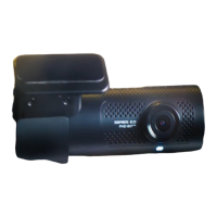
Verify camera angle by checking for 2 visible recessed lines below the lens.
Apply vehicle protection to front seats, dashboard, and center console.
Ensure the front windshield is at least 50°F (10°C) before installation.
For PPO installations, use the 3D hard template 'H' (RAV22-0020) and follow specific steps.
For dealer installations or if template is unavailable, follow steps (g) through (i).
Clean the windshield area next to the TSS cover using window cleaner and a lint-free cloth.
Insert the 3D Template between the TSS cover and windshield glass, ensuring a snug fit.
Stick the mounting plate on the windshield, aligning with the template edges and pressing firmly.
Gently pull the 3D hard template towards the windshield base to slide it out.
For dealer installations, cut the paper template and affix it to the windshield using tape for alignment.
Reference the TSS cover to align the paper template and affix it to the windshield with tape.
Stick the mounting plate on the windshield following the reference lines on the paper template.
Remove the paper template by sliding it towards the lower edge of the windshield and clean any residue.
Remove Sun Visor Hooks from both driver and passenger sides of the Map Light Console.
Twist the Visor Hook Anti-Clockwise and pull down to release the hook component.
After removing the hook, release the tabs and pull out the base using needle nose pliers.
Pull down the roof console firmly from the rearward edge to release the rear and front clips.
A plastic panel removal tool may be used to pull down the console.
Do not pry against the headliner to avoid visible damage.
Once detached, disconnect the wire harness from the roof console and place it safely.
Inspect the console clips and replace if damaged (P/N: 90467-09240, 4 PCS).
Rotate the mirror approximately 45 degrees to improve access to the TSS cover sides.
Hold the TSS Cover and move it downwards towards the wiper cowl area by 10 mm for better access.
Pull down the smaller inset cover around the mirror mount to detach it from the main TSS cover.
Slide the TSS main cover down from the TSS cover base towards the wiper cowl area to remove it.
Disconnect the mirror power harness from the 10-pin connector on the passenger side.
Install the Y-harness by connecting the vehicle's power mirror connector and the male mirror connector.
Apply the supplied Foam Tape to insulate the connector from rattles.
Feed the Y-harness connector to the TSS area and insert it into the female mirror connector.
Pull the remaining harness slack back into the headliner / map light console area.
From the driver's side, locate the notch in the front edge of the headliner for routing.
Route the Dash Cam pigtail through the notch or similar area into the headliner without creasing.
Feed the Dashcam harness through to the open Map Light Console area.
Connect the Dashcam pigtail harness to the newly fitted Y-harness.
Apply supplied Foam Tape to insulate the connectors from rattles.
Push the TSS cover up along the windshield to engage mounting clips into the cover base.
Hook the mirror cover plate's front hooks into the TSS main cover opening and push up to engage clips.
The Hang Tag should only be removed by the end user and is intended to block recording initially.
Do NOT remove the hang tag; handle it with care to prevent accidental removal.
IMPORTANT: Remove the Semi-Transparent Blue Film protective cover from the camera lens before fitting.
Observe the shape of the T-hook features for the Dashcam to lock onto; hooks face upwards.
Affix the Dashcam to the window by sliding onto the 4 T-hooks and allowing the clip to engage.
Hook the Dashcam wire extension cover hooks into the leading edge of the headliner.
Swing the Dashcam unit up towards the base plate, checking alignment of the 4 T-hooks.
Push the dashcam unit towards the windshield to ensure all 4 T-hooks are correctly positioned.
Slide the Dashcam down towards the T-hooks to engage the securing clip and adjust harness cover.
Protect connector pairs and fuse holders with foam tape to minimize rattle concerns.
Secure the Y-harness and fuse holders against existing harnesses at the map light/sunglasses pocket opening.
Secure Dashcam Pigtail harnesses against existing harnesses, looping and bundling as required.
Ensure the console connection is free and bundled harnesses do not obstruct the map light connector.
Take care not to cause bulging in the headliner; adjustments to the bundle may be needed.
Do not block clip holes in the body structure to ensure proper roof console fit.
Snip off extra cable-tie length to prevent rattles or squeaks from loose ends.
Reconnect the overhead console harness and test map lights and sunroof controls.
Check console clips are present and aligned. Use a panel tool to pry out any remaining clips in the roof.
Push the console upwards on all 4 corners to lock it, observing headliner marks for alignment.
Be careful aligning the clips to holes to avoid damage during reinstallation.
Insert the clip bases on both sides of the map light console until they snap securely into place.
Insert the visor clips, starting with the opening in anti-clockwise position, then rotate clockwise to lock.
Reconnect the Negative Battery Cable and replace cover trim if necessary.
Torque the negative battery cable connection to 5.4 N•m (48 in-lbsf).
CAUTION: Do not touch the positive terminal with any tool during reconnection.
Place the Owner's Manual ('Quick Start Guide') in the glove box with other vehicle owner's manuals.
Adjust camera angle if the 2 visible recessed lines under the lens are not as intended.
DO NOT try to force the lens to move the camera; it is locked and can be damaged.
Use a 1.5 mm Allen Key to turn screws counterclockwise 2-3 turns to release pressure on locks.
Raise or lower the camera view angle to see two recessed rib lines below the camera lens.
Once angle is correct, retighten locking screws on each side and reconfirm recessed rib lines.
Optionally use the Live View feature of the phone app to confirm the view angle.
When connecting for the first time, choose 'Remind Me Next Time' for the Wi-Fi password prompt.
| Brand | Toyota |
|---|---|
| Model | PT949-08231 |
| Category | Dash Cameras |
| Language | English |