02
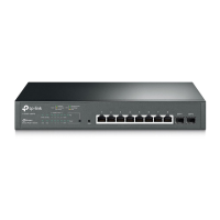
Gigabit L2 Managed Switch
Introduction
LEDs
LED Status Indication
PWR
On The switch is powered on
Off
The switch is powered off or power supply is
abnormal
Flashing Power supply is abnormal
SYS
Flashing The switch works properly
On/Off The switch works improperly
10/100/1000M
On
Green
A 1000Mbps device is linked to the corresponding
port, but no activity
Yellow
A 10/100Mbps device is linked to the corresponding
port, but no activity
Flashing Data is being transmitted or received
Off Not linked
SFP1, SFP2
On
A 1000Mbps device is linked to the corresponding
port, but no activity
Flashing Data is being transmitted or received
Off Not linked
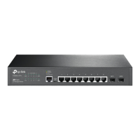
Console (RJ-45) Port
Designed to connect with the serial port of a computer or terminal for monitoring
and configuring the switch.
Console (USB) Port
Designed to connect with the USB port of a computer for monitoring and
configuring the switch. The switch has an RJ-45 console port and a micro-USB
console port available. Console input is active on only one console port at a
time. By default, the micro-USB connector takes precedence over the RJ-45
connector.
10/100/1000Mbps RJ45 Port
Designed to connect to the device with a bandwidth of 10Mbps, 100Mbps
or 1000Mbps. Each 10/100/1000Mbps RJ45 port has a corresponding
10/100/1000M LED.
SFP Port
Designed to install the SFP module. T2500G-10TS features 2 individual SFP ports
and supports 1000M SFP module connection only.
 Loading...