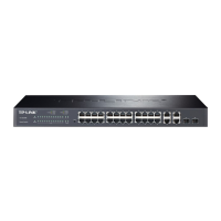
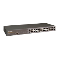
The front p
anel of TL-SL2218 is shown as Figure 2-2.
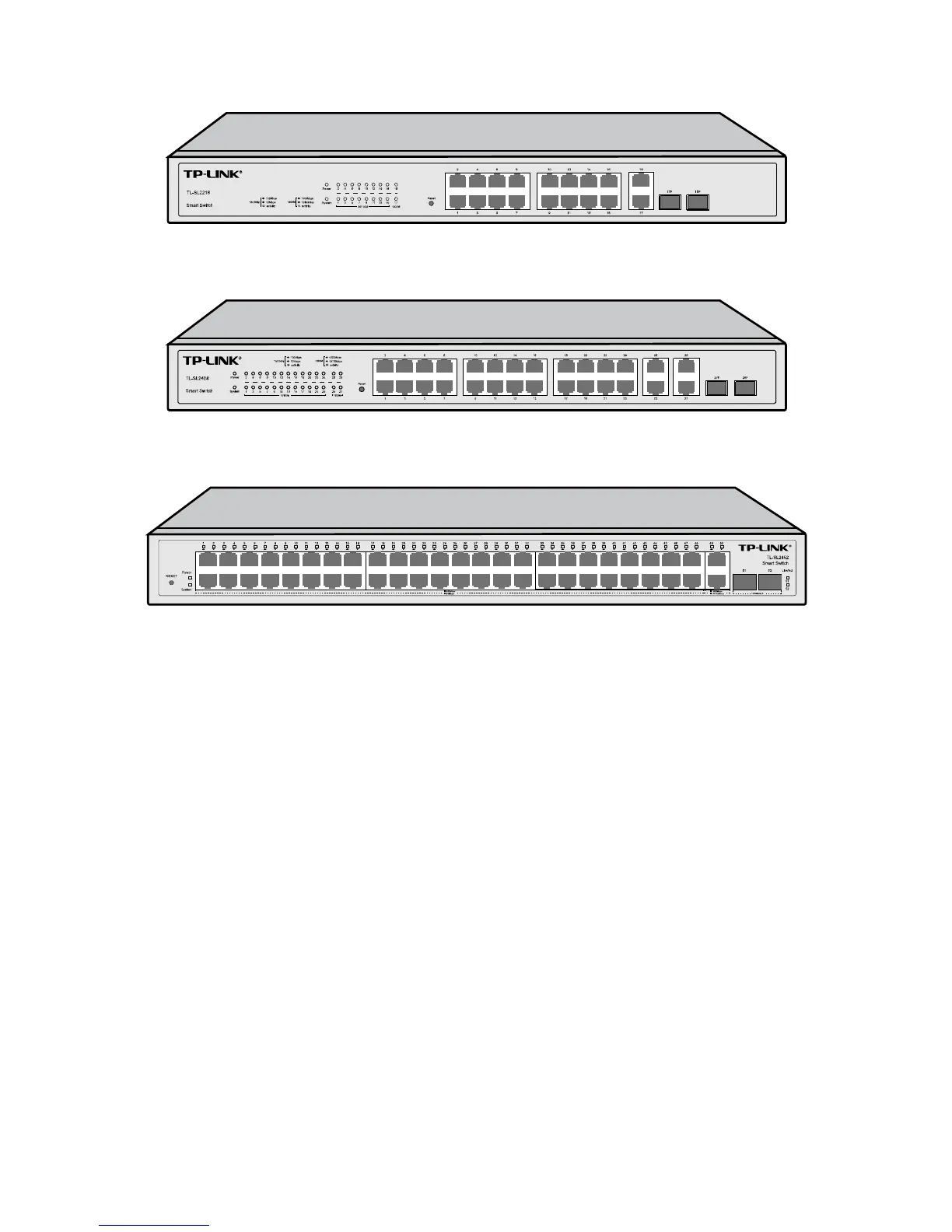
Figure 2-2 Front Panel of TL-SL2218
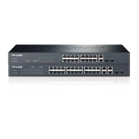
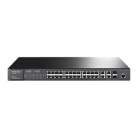
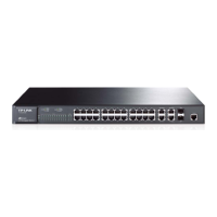
The front panel of TL-SL2428 is shown as Figure 2-3.
Figure 2-3 Front Panel of TL-SL2428
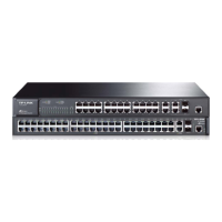
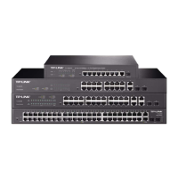
The front panel of TL-SL2452 is show as Figure 2-4.
Figure 2-4 Front Panel of TL-SL2452
The following parts are located on the front panel of the switch:
Reset: Press this button for five seconds or above to reset the software setting back to factory
default setting.
10/100Mbps Ports: Designed to connect to the device with a bandwidth of 10Mbps or
100Mbps. Each has a corresponding 10/100M (10/100Mbps) LED.
10/100/1000Mbps Ports: Designed to connect to the device with a bandwidth of 10Mbps,
100Mbps or 1000Mbps. Each has a corresponding 1000M (1000Mbps) LED.
SFP Ports: Designed to install the SFP module. TL-SL2218/TL-SL2428 features some SFP
transceiver slots that are shared with the associated RJ45 ports. The associated two ports are
referred as a "Combo" port, which means they cannot be used simultaneously, otherwise only
SFP port works. Meanwhile, the associated two ports share the same LED. For TL-SL2218,
Port 17 shares the same LED with Port 17F and Port 18 shares the same LED with Port 18F;
for TL-SL2428, Port 27 shares the same LED with Port 27F and Port 28 shares the same LED
with Port 28F.
6