2119
e. Measuring Resistance
WARNING!
Do not attempt to make resistance measurements with
circuit energized. For best results, remove resistor
completely from circuit before attempting to measure it.
NOTE:
To make accurate low ohm measurements, short the
ends of the test leads together and record the resistance
reading. Deduct this value from actual readings.
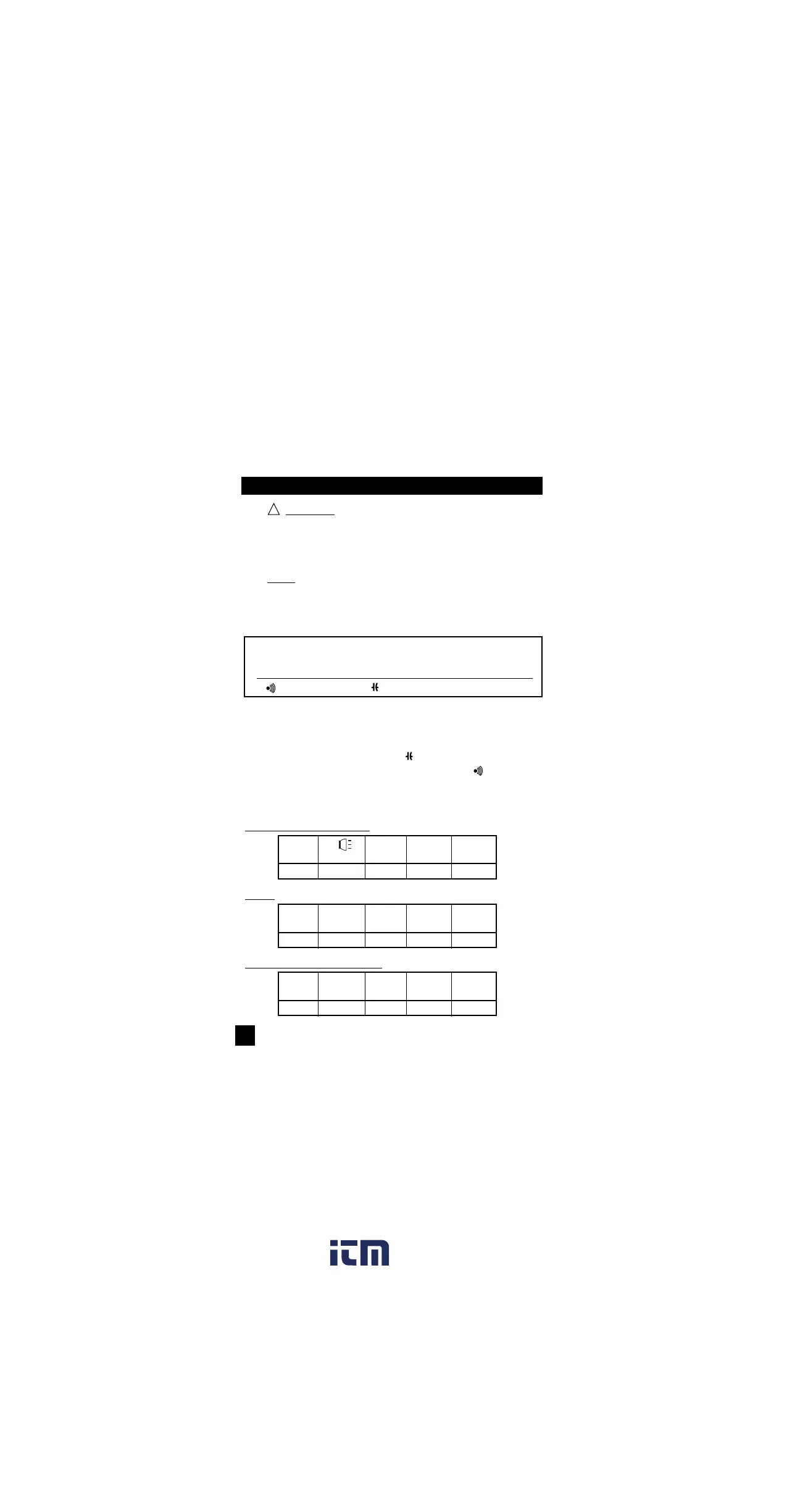
Instrument set-up:
FUNCTION BLACK RED MINIMUM MAXIMUM
TEST LEAD TEST LEAD READING READING
Ω COM VΩ 0.1Ω 30.00MΩ
Measurement Procedure:
1. Disconnect power to circuit to be measured.
2. Plug black test lead into the COM input jack.
3. Plug red test lead into VΩ input jack.
4. Set the rotary switch on the 440 to the Ω function.
5. Connect the test leads to the circuit to be measured.
6. Read the resistance value on the 440.