EasyManuals Logo

TPI Scope Plus User Manual

TPI Scope Plus
44 pages
To Next Page IconTo Next Page
To Previous Page IconTo Previous Page
Page #23 background imageLoading...
Page #23 background image
26
TRIG LEVER: +00
1mS/DIV󳚔 SLOPE:
+
TRIG LEVER: +00
1mS/DIV󳚔 SLOPE:
+
TRIG LEVER: +00
1mS/DIV󳚔 SLOPE:
+
TRIG LEVER: +00
1mS/DIV󳚔 SLOPE:
+
j. Component Test
Use Component Test to measure the characteristics of a
passive component (in or out of circuit, no power applied).
The 440 provides an AC stimulus signal to the component and
plots the voltage drop against the current measurement. The
resulting pattern provides information about passive circuit
condition.
2Hz 20Hz 200Hz
F1 F2 F3 F4 F5
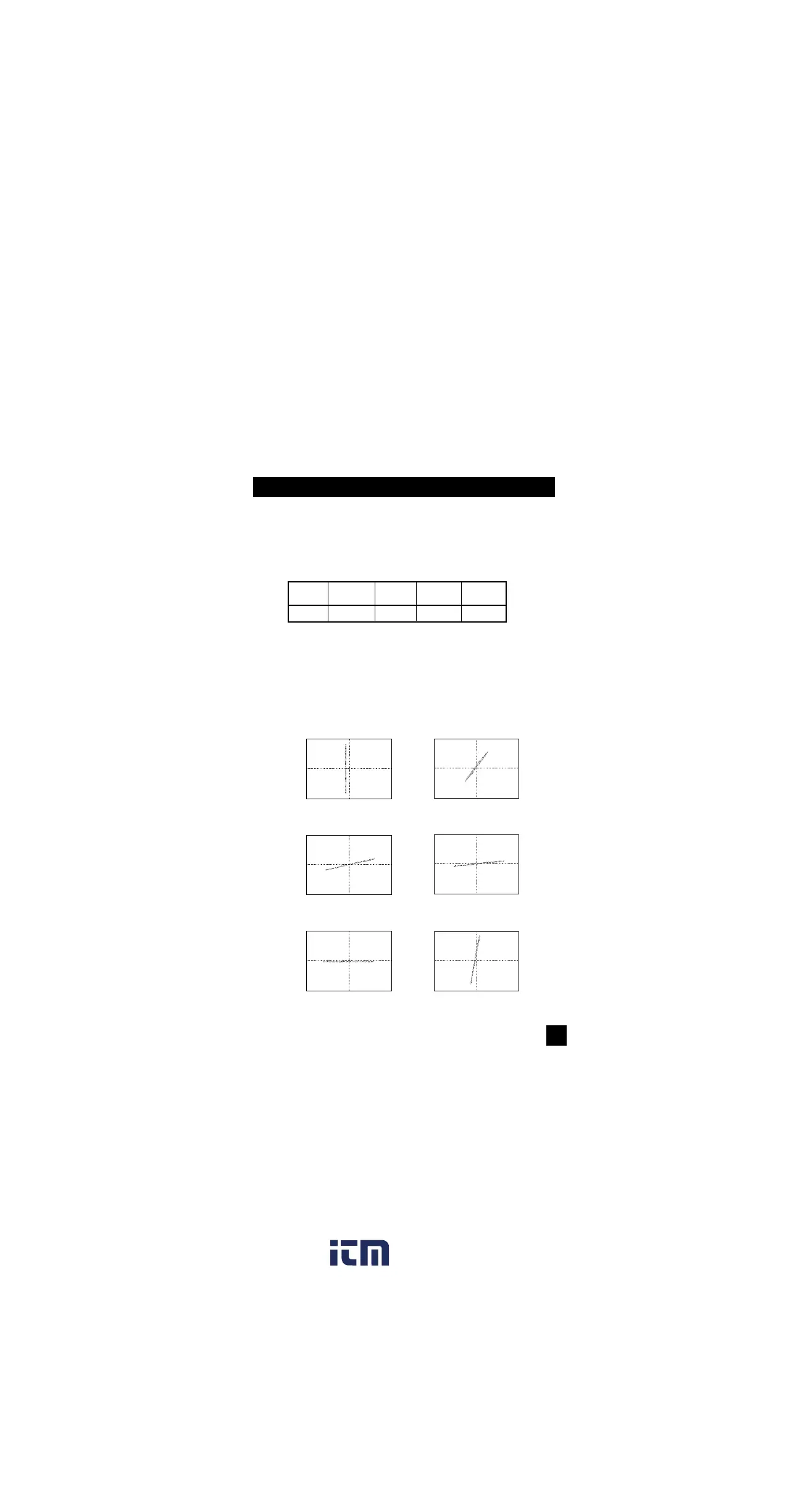
Diagrams are displayed on the LCD that can be used to rough-
ly identify components being measured. The diagrams below
show typical signatures for the components that are indicated.
Some components may be difficult to distinguish due to simi-
larities in pattern, however, the determination of a good or bad
component can be made.
NOTE: RESISTOR 0 RESISTOR 1k
RESISTOR 10k RESISTOR 20k
TRIG LEVER: +00
1mS/DIV󳚔 SLOPE:
+
TRIG LEVER: +00
1mS/DIV󳚔 SLOPE:
+
RESISTOR 100k RESISTOR 200
24
www. .com
information@itm.com1.800.561.8187

Questions and Answers:

Question and Answer IconNeed help?

Do you have a question about the TPI Scope Plus and is the answer not in the manual?

TPI Scope Plus Specifications

General IconGeneral
BrandTPI
ModelScope Plus
CategoryTest Equipment
LanguageEnglish