2220
f. Measuring Diodes
CAUTION!
Do not attempt to make diode measurements with circuit
energized. The only way to accurately test a diode is to
remove it completely from the circuit before attempting to
measure it.
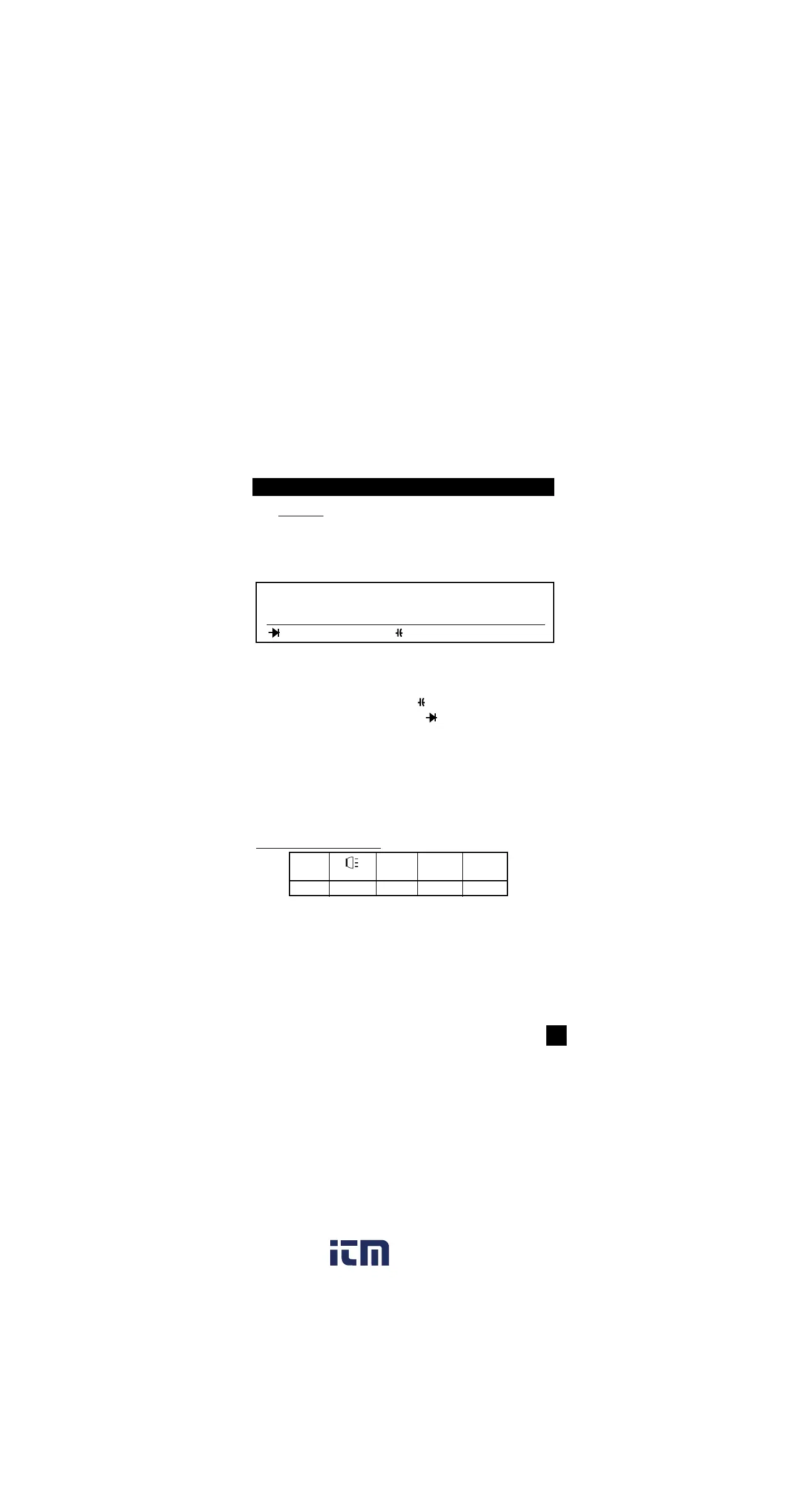
Instrument set-up:
FUNCTION BLACK RED MINIMUM MAXIMUM
TEST LEAD TEST LEAD READING READING
COM VΩ 0.001V 2.000V
Measurement Procedure:
1. Disconnect power to circuit to be measured.
2. Plug black test lead into the COM input jack.
3. Plug red test lead into VΩ input jack.
4. Set the rotary switch to the function.
5. Connect black test lead to the banded end of the diode
and the red test lead to the non-banded end of the diode.
6. Reading on display should be between 0.5 and 0.8 volts.
7. Reverse test lead connections in 5 above.
8. Reading on the display should be OUCH (Overload).
NOTE: If diode reads 0 in both directions, diode is shorted.
If diode reads OUCH in both directions, diode is open.
Optional DMM Functions (refer to page 27)
POLA.
CHECK
F1 F2 F3 F4 F5