©1999 Trace Engineering
Figure G
Both AC Line and Inverter OFF
3.0 OPERATION
25
Figure 27
Inverter In Circuit (Normal Operation)
Figure 28
Inverter Out of Circuit
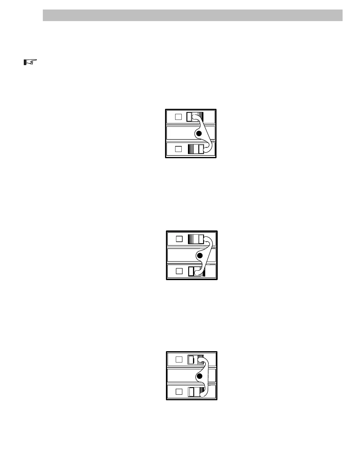
Figure 29
Both AC Line and Inverter OFF
Under normal operation, the INVERTER OUTPUT breakers are ON.
NOTE: Only one AC Disconnect/Bypass breaker is illustrated below. For dual inverter models, the second
breaker set controls inverter 2 in exactly the same way.
Inverter In Circuit
In this configuration, power passes through the inverter to the connected load. If an ac line failure occurs,
dc from the batteries is routed through the inverter to maintain the load.
Inverter Out of Circuit
In this configuration, power passes directly to the connected load, bypassing the inverter. This allows the
inverter to be removed from service without affecting the connected load. If an ac line failure occurs while the
inverter is switched off, the load will be dropped.
Both AC Line and Inverter OFF
In this configuration, power from both the ac utility and inverter is removed from the circuit. This allows
the inverter, the connected loads, or any other installed equipment beyond the AC Disconnect/Bypass switch
to be serviced.
INVERTER OUTPUT
INVERTER BYPASS
BREAKER OFF
Bypass circuit is de-energized.
BREAKER ON
Inverter circuit is energized.
INV 1
60
OFF
DD
OFF
60
0N
2903-00-016
INVERTER OUTPUT
INVERTER BYPASS
BREAKER ON
Bypass circuit is energized.
BREAKER OFF
Inverter circuit is de-energized.
INV 1
OFF
DD
OFF
2903-00-017
60
60
INVERTER OUTPUT
INVERTER BYPASS
BREAKER OFF
Bypass circuit is de-energized.
BREAKER OFF
Inverter circuit is de-energized.
INV 1
OFF
DD
OFF
2903-00-018
60
60
AC Disconnect Module (continued)