©1999 Trace Engineering
2.0 INSTALLATION
AC WiringDR Series Single Inverter Models
AC Input/Output Wiring To AC Bypass Box
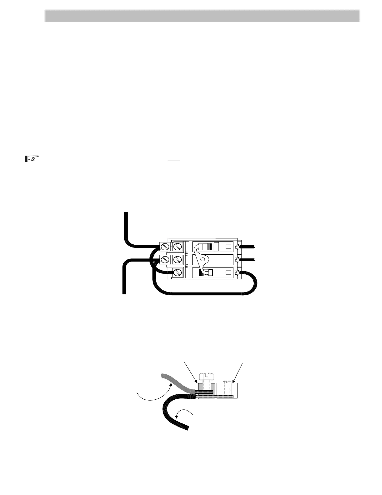
Connect the Ground wire to the Ground block in the AC Disconnect/Bypass Box. Connect the other end
to the sub-panel's Ground Bar.
Connect the Hot (input) wire from the utility service panel as indicated in Figure 22.
Connect the Hot wire (output) as indicated in Figure 22. Connect the other end of this wire to the input
breaker in the sub-panel.
Connect the Neutral wire to the Neutral block in the AC Disconnect/Bypass Box. Connect the other end to
the sub-panel's Neutral Bar.
Torque service crimps to 45 in-lb (3.75 ft-lb), (5 N-m).
NOTE: The Ground and Neutral are bonded only at the main utility service panel.
Figure 22
AC Input/Output Wiring (Single Inverter Models)
19
NOTE:
DO NOT REMOVE
FACTORY WIRING!
IN
INV
OUT
INV
0N
60
OFF
D
60
OFF
D
TO SUB-PANEL
(LOADS)
HOT
FROM UTILITY OR
GENERATOR
HOT
To Sub-panel
Loads
(HOT)
From Utility or
Generator
(HOT)
Figure 22A
Breaker Terminal Lug Detail (side view)
Breaker Lug
Service Crimp
Existing Factory Wiring
Added Input or
Output Wire
2906-00-026A