©1999 Trace Engineering
Figure 21
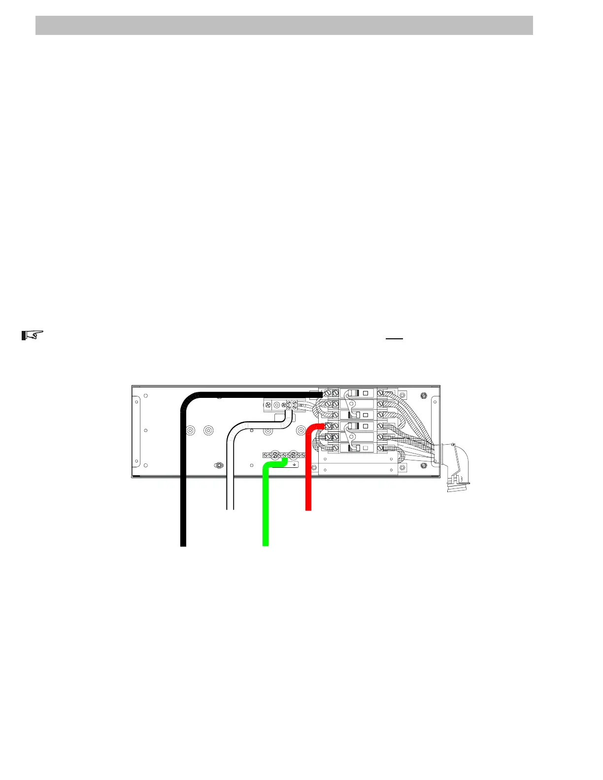
AC Output Wiring
AC WiringDR Series Dual Inverter Models (continued)
AC Output Wiring To The AC Bypass Box
Select a convenient knockout on the AC Disconnect/Bypass Box for installing conduit which will carry the
wires from the inverters output to the sub-panel.
Use #6 AWG THHN wire (minimum) and route it through the conduit to the between the AC Disconnect/
Bypass Box and the sup-panel.
Connect the Ground wire to the Ground block in the AC Disconnect/Bypass Box. Connect the other end
to the sub-panel's Ground Bar.
Connect the L1 (Hot-black) wire to the INVERTER 1 HOT OUT L1 (top ac breaker) as indicated in
Figure 21.
Connect the L2 (Hot-red) wire to the INVERTER 2 HOT OUT L2 (top ac breaker) as indicated in Figure
21.
Connect the Neutral wire to the Neutral block in the AC Disconnect/Bypass Box. Connect the other end to
the sub-panel's Neutral Bar.
Torque service crimps to 45 in-lb (3.75 ft-lb), (5 N-m).
NOTE: The Ground and Neutral are bonded at the main utility service panel only.
NOTE:
DO NOT REMOVE
FACTORY WIRING!
NEUTRAL NOT BONDED TO GROUND
RED#6AWG
WHITE #6AWG
INV 1
INV 2
D
OFF
60
D
OFF OFF
D
60
D
OFF
6060
0N0N
SOURCE AND LOAD
INPUT AND OUTPUT
NEUTRAL
GROUND
2903-00-023
L2 to Sub-panel
(Loads)
HOT
Ground to
Sub-panel
(Loads)
Neutral to
Sub-panel
(Loads)
L1 to Sub-
panel (Loads)
HOT
18
2.0 INSTALLATION