©1999 Trace Engineering
AC WiringDR Series Dual Inverter Models (continued)
AC Input Wiring To The AC Bypass Box
Select a convenient knockout on the AC Disconnect/Bypass Box for installing conduit which will carry the
wires from the main utility panel or generator.
Install a 60 amp circuit breaker in the main utility service panel for each ac input to the inverter(s).
Use #6 AWG THHN wire (minimum) and route it through the conduit to the AC Disconnect/Bypass Box.
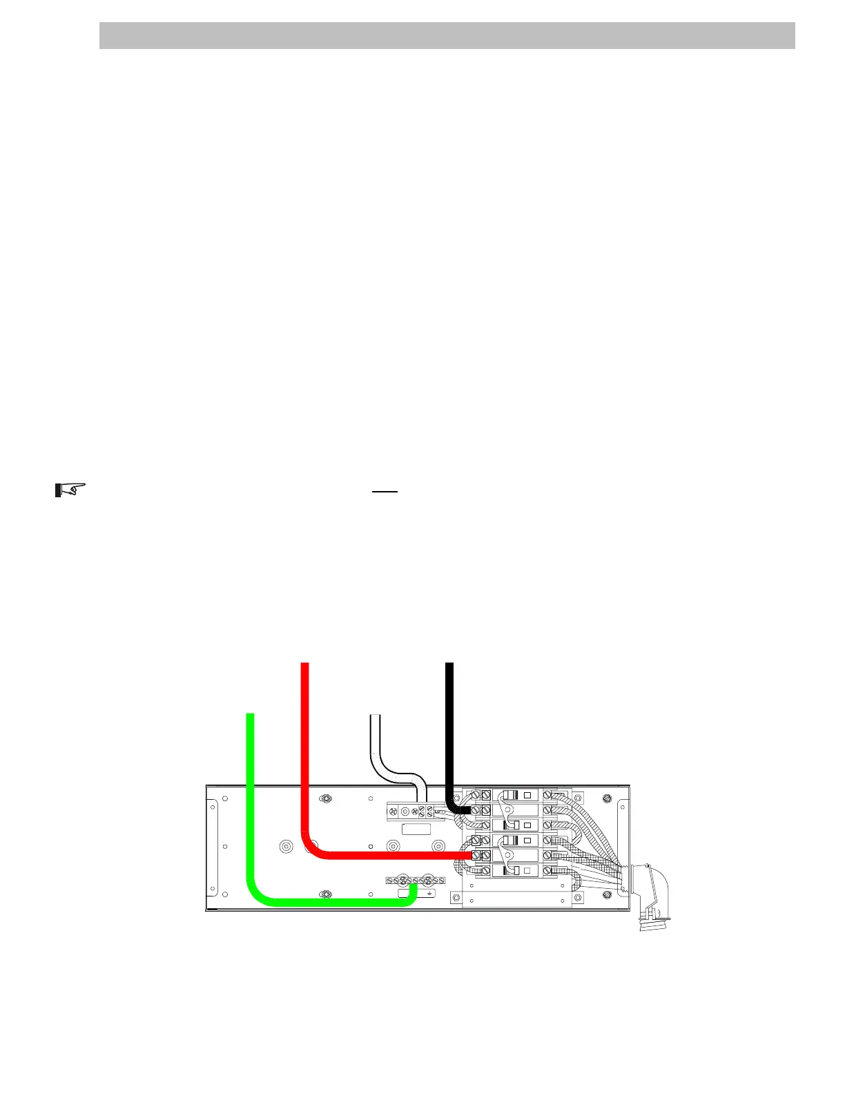
Connect the Ground from the main utility box to the ground terminal in the AC Disconnect/Bypass Box as
indicated in Figure 20.
Connect the L1 (Hot-black) wire to the INVERTER 1 HOT IN L1 (center ac breaker) as indicated in
Figures 18 and 20.
*Connect the L2 (Hot-red) wire to the INVERTER 2 HOT IN L2 (center ac breaker) as indicated in
Figures 18 and 20.
Connect the Neutral wire from the main utility box to the Neutral block in the AC Disconnect/Bypass Box
as indicated in Figure 20.
Torque service crimps to 45 in-lb (3.75 ft-lb), (5 N-m).
NOTE: The Ground and Neutral are bonded only at the main utility service panel.
Figure 20
AC Input Wiring
NEUTRAL NOT BONDED TO GROUND
RED#6AWG
WHITE #6AWG
INV 1
INV 2
D
OFF
60
D
OFF OFF
D
60
D
OFF
6060
0N0N
SOURCE AND LOAD
INPUT AND OUTPUT
NEUTRAL
GROUND
Ground from
Utility or
Generator
L1 from Utility
or Generator
HOT
L2 from Utilit
or Generator
HOT
Neutral from
Utility or
Generator
2903-00-022A
NOTE:
DO NOT REMOVE
FACTORY WIRING!
2.0 INSTALLATION
17