©1999 Trace Engineering
AC Input/Output Wiring to the Utility and Sub-panel
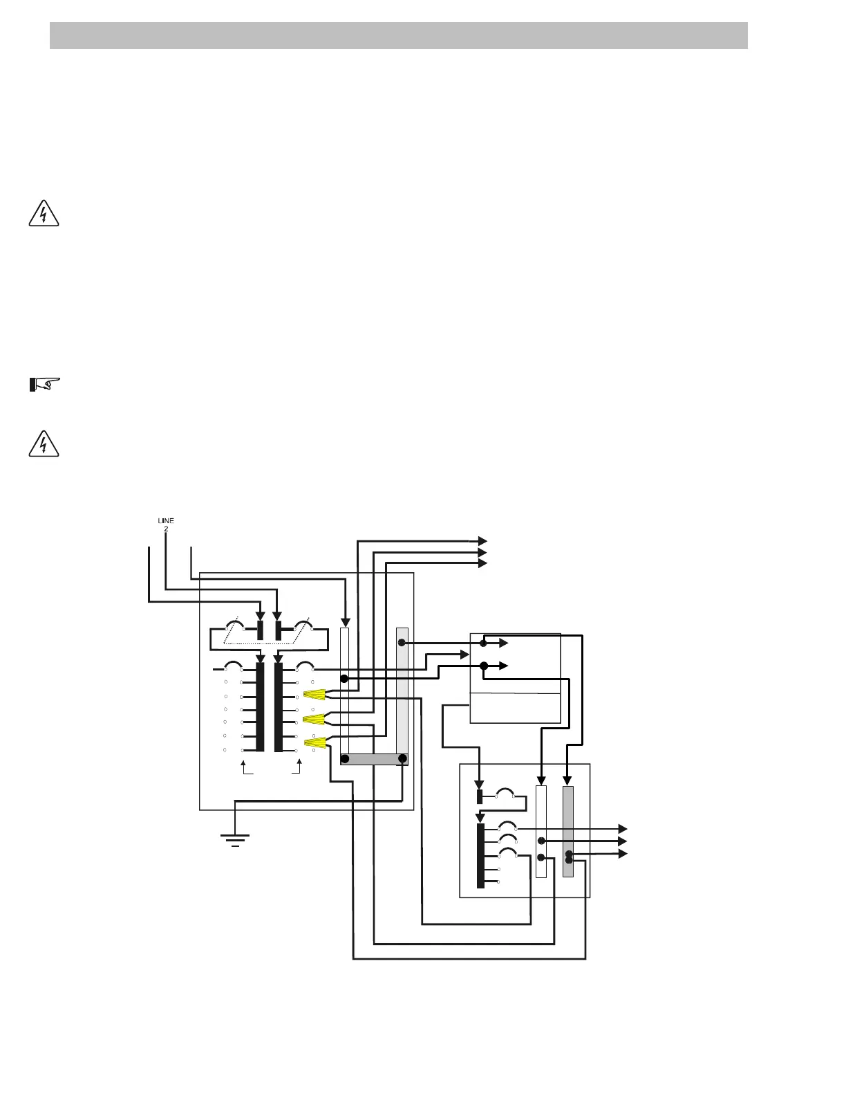
The following diagrams illustrate wiring the Power Panels to the utility service box and to the sub-panel.
Existing wiring can be used by routing the output of the sub-panel back into the main utility service box and
wire-nut splicing these wires to the existing house wiring. Refer to Figures 23 (single inverter 120 V ac), 24A
and 24B (dual inverter (120/240 V ac) for general wiring diagrams.
WARNING: ENSURE ALL POWER IS DISCONNECTED IN THE MAIN UTILITY BREAKER BOX BEFORE
PROCEEDING.
Select the circuits that require backup power and disconnect them from the main utility breaker.
Mark the breaker as "not used" in the main utility panel.
Wire splice these connections to the output from the sub-panel.
Mark the sub-panel with an appropriate name for this circuit.
NOTE: Check local codes. Wire-nut splices may not be allowed in the main utility panel in some areas. In
these cases, use a separate junction box for these connections and cover with a blank plate.
WARNING: REPLACE CIRCUIT BREAKERS (IN THE SUB-PANEL) WITH EQUALLY RATED BREAKERS.
NEVER INCREASE THE CIRCUIT BREAKER AMPERAGE RATING.
Figure 23
AC Input/Output UtilitySub-panel Wiring (Single Inverter Models)
20
FROM
UTILITY
AC BYPASS BOX
MAIN PANEL
120 V AC FROM
INVERTER
UTILITY FEED
FROM METER
SUB PANEL
POWER PANEL
Single Inverter
GROUND
NEUTRAL
120 V AC LINE IN
LINE OUT
120 V AC LINE OUT
NEUTRAL
GROUND
LINE OUT
NEUTRAL
GROUND
NEUTRAL
NEUTRAL
LINE
1
LINE OUT
GROUND
EXISTING 120 V ac HOUSE
WIRING (Each circuit)
120 V AC BACKUP POWER
TO LOAD
(NEW WIRING)
DISCONNECT
MAIN
BREAKER
NOTE: FOR ILLUSTRATIVE PURPOSES ONLY.
BREAKER BOXES VARY DEPENDING ON APPLICATION.
MAIN PANEL WIRING TO NON-CRITICAL LOADS
IS NOT ILLUSTRATED.
EARTH GROUND
120 V AC BACKUP POWER
TO LOAD
120 V AC
120 V AC
240 V AC
GROUND
CAUTION:
NEUTRAL BONDED TO GROUND
IN MAIN PANEL ONLY!
NEUTRAL
2903-00-028
2.0 INSTALLATION