12
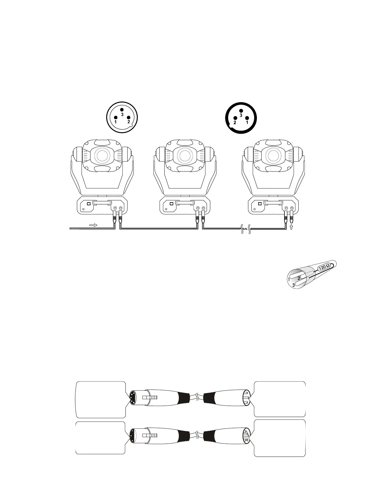
Data Link DMX-512
For data, this fixture uses 3 pin XLR (Cannon) type connectors and shielded twisted pair cable
approved for EIA-422/EIA485 use. Fixtures are connected in Daisy Chain topography with only
one data source and no branching is allowed. Systems using 5 pin DMX interfaces can be
accommodated by purchasing 3-to-5 pin adapters or building adapter cables.
Data Terminator
A Data Terminator can be connected to the DATA OUT connection
of the last fixture to reduce the effects of noise in the signal; it is not
required for all installations. To make a Data Terminator, connect a
120-ohm ¼ watt resistor across pin 2, Data Negative (S-) and pin 3,
Data positive (S+). A qualified technician can determine if a Data
Terminator is needed.
Adapter 5-to-3 pin
Numbers designating each pin can be found on connectors. Converting between the two
XLR types is done in a pin-to-pin fashion. Connect the shields to pin 1, then connect pin
2 to pin 2 and pin 3 to pin 3. This is true for converting either 5 to 3 pin or 3 to 5 pin
regardless of either connector’s gender. Pins 4 and 5 are not used on the 5 pin XLR
connectors.
5Pin XLR (Plug)
Pin 1: GND(Sheild)
Pin 2: Signal(-)
Pin 3: Signal(+)
Pin 4: N/C
Pin 5: N/C
3 XLR (S )
Pin 1: GND(Sheild)
Pin 2: Signal(-)
Pin 3: Signal(+)
Pin ocket
5 Pin XLR (Socket)
Pin 1: GND(Sheild)
Pin 2: Signal(-)
Pin 3: Signal(+)
Pin 4: N/C
Pin 5: N/C
3 XLR (Plug)
Pin 1: GND(Sheild)
Pin 2: Signal(-)
Pin 3: Signal(+)
Pin
-
1
2
3
- Ground
- Signal (-)
- Signal (+)
XLR Connector - Plug:
DMX-
U
1
2
3
- Ground
- Signal (-)
- Signal (+)
LR Connector - Socket:
DMX512
120