EasyManua.ls Logo

Trane Technologies 4TWA4048A4000A - User Manual

Default Icon
24 pages
Print Icon
To Next Page IconTo Next Page
Loading...
SSAAFFEETTYY WWAARRNNIINNGG
Only qualified personnel should install and service the equipment. The installation, starting up, and servicing of heating, ventilating, and air-conditioning
equipment can be hazardous and requires specific knowledge and training. Improperly installed, adjusted or altered equipment by an unqualified person
could result in death or serious injury. When working on the equipment, observe all precautions in the literature and on the tags, stickers, and labels that
are attached to the equipment.
May 2020
1188--BBCC9977DD11--11DD--EENN
Split System Heat Pump
3-Phase, 230V
3-Phase, 460V
220088--223300VV MMOODDEELL
4TWA4036A3000A
4TWA4042A3000A
4TWA4048A3000A
4TWA4060A3000A
446600VV MMOODDEELL
4TWA4036A4000A
4TWA4042A4000A
4TWA4048A4000A
4TWA4060A4000A
NNoottee:: “Graphics in this document are for representation
only. Actual model may differ in appearance.”
Installer’s Guide
Question and Answer IconNeed help?

Do you have a question about the Trane Technologies 4TWA4048A4000A and is the answer not in the manual?

Summary

Safety Section

Hazardous Voltage Warning

Warning about severe personal injury or death due to electrical hazards.

Refrigerant Oil Warning

Warning about property damage, injury, or death from refrigerant oil handling.

Contains Refrigerant Warning

Warning about injury or damage from refrigerant under pressure.

Grounding Required Caution

Warning about equipment damage or injury if grounding is not used properly.

Service Valves Warning

Warning about abrupt release of system charge from service valves.

Brazing Requirements

Ensure leak test is negative if using mechanical connections; braze all joints.

Refrigerant Line Brazing

Refrigerant Line Leak Check

Refrigerant Line and Indoor Coil Evacuation

Service Valves

System Start Up

System Charge Adjustment

Subcooling Charging in Cooling

Charging the Unit

Checkout Procedures

Overview

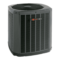
This document is an installer's guide for a Trane Split System Heat Pump, available in 3-phase, 230V and 3-phase, 460V models. The guide provides essential information for the safe and proper installation, start-up, and servicing of these outdoor condensing units.

Function Description:

The Trane Split System Heat Pump is designed to provide comfortable, energy-efficient indoor environments for residential applications. It functions as part of a split system, requiring an indoor evaporator coil and refrigerant lines to operate. The guide emphasizes the importance of installing Trane-approved matched indoor and outdoor systems to achieve maximum efficiency, optimum performance, and best overall reliability.

Important Technical Specifications:

  • Models Covered:
    • 208-230V: 4TWA4036A3000A, 4TWA4042A3000A, 4TWA4048A3000A, 4TWA4060A3000A
    • 460V: 4TWA4036A4000A, 4TWA4042A4000A, 4TWA4048A4000A, 4TWA4060A4000A
  • Refrigerant: R-410A, which operates at 50-70% higher pressures than R-22. It uses POE oil.
  • Refrigerant Line Length: Maximum total length of refrigerant lines from outdoor to indoor unit should not exceed 150 feet (including lift).
  • Vertical Change (Lift): Maximum vertical change should not exceed 50 feet.
  • Electrical:
    • Low Voltage Wiring:
      • 18 AWG: Max. 150 Ft.
      • 16 AWG: Max. 225 Ft.
      • 14 AWG: Max. 300 Ft.
    • High Voltage: Power supply must match equipment nameplate.
  • Defrost Control: Selectable termination temperature (47°F as shipped, 70°F with Jumper J2 cut).
  • Charging Method: Subcooling in cooling mode is the only recommended method for charging between 55°F and 120°F ambient outdoor temperature. Indoor temperature should be kept between 70°F and 80°F for best results.
  • Indoor Blower Configuration: Variable speed outdoor units require the indoor unit to be configured for 400 CFM/TON.

Usage Features:

  • Installation Considerations:
    • Location:
      • Top discharge area unrestricted for at least 5 feet above the unit.
      • At least 3 feet clearance in front of control box and any service-requiring side.
      • Avoid locations near bedrooms, windows, or areas where condensation/defrost vapor may annoy.
      • Minimum 12 inches from walls or shrubbery for adequate airflow.
      • Far enough from structures to prevent roof runoff or icicles from falling on the unit.
    • Cold Climate (Heat Pump Only):
      • Elevate unit 3-12 inches above pad/rooftop to allow snow/ice drainage.
      • Ensure drain holes in base pan are not obstructed.
      • Avoid snow drift locations; install a snow drift barrier if necessary.
    • Coastal Considerations: For installations within one mile of salt water, the BAYSEAC001 (Seacoast Kit) is required for models without factory-supplied Seacoast Salt Shields.
    • Pad Installation: Pad should be at least 1 inch larger than the unit on all sides, separate from any structure, level, high enough for drainage, and compliant with codes.
  • Refrigerant Line Routing:
    • Vapor line must always be insulated.
    • Liquid line and vapor line should not be in direct metal-to-metal contact.
    • Insulating the liquid line in attic spaces may improve performance.
    • Comply with national, state, and local codes for isolating line sets.
    • Use isolation type hangers when fastening lines to joists/framing.
    • Isolate lines from all ductwork.
    • Minimize 90° turns.
  • System Start-Up:
    • Set thermostat to OFF.
    • Turn on electrical power disconnects for indoor and outdoor units.
    • Wait one (1) hour before starting if compressor crankcase heater accessory is used and outdoor ambient is below 70°F.
    • Set thermostat to ON after the waiting period.

Maintenance Features:

  • Safety Precautions:
    • Hazardous Voltage: Disconnect all electric power and follow lockout/tagout procedures before servicing.
    • Refrigerant Oil (R-410A/POE): Use only R-410A approved service equipment. Never break a vacuum with air. Change driers when opening the system for component replacement. Replace compressor oil if the system has been open to the atmosphere for more than 4 hours.
    • Hot Surface: Do not touch the top of the compressor.
    • Contains Refrigerant: Recover refrigerant to relieve pressure before opening the system.
    • Grounding Required: Reconnect all grounding devices after service.
    • Service Valves: Exercise extreme caution when opening suction and liquid line service valves. Turn valve stem counterclockwise only until it contacts the rolled edge; no torque is required.
    • Brazing: Ensure all joints are brazed, not soldered, especially if reusing existing refrigerant lines. Perform a leak test.
    • High Leakage Current: Earth connection is essential before connecting electrical supply.
  • Refrigerant Line Brazing:
    • Debur pipe ends and clean internal/external surfaces.
    • Remove pressure tap cap and valve core from service valves.
    • Purge lines and indoor coil with dry nitrogen.
    • Wrap a wet rag around the valve body to prevent heat damage during brazing.
    • Check liquid line filter drier for correct directional flow (away from outdoor unit, toward evaporator coil).
    • Continue dry nitrogen purge until brazing is complete.
    • Remove wet rag before stopping purge.
    • Replace valve cores after valves have cooled.
  • Refrigerant Line Leak Check:
    • Pressurize lines and evaporator coil to 150 PSIG with dry nitrogen.
    • Check for leaks with soapy solution at brazed locations.
    • Remove nitrogen pressure and repair any leaks.
  • Refrigerant Line and Indoor Coil Evacuation:
    • Evacuate until micron gauge reads no higher than 350 microns.
    • Close valve to vacuum pump.
    • Evacuation is complete if micron gauge does not rise above 500 microns in one minute.
    • Blank off vacuum pump and micron gauge, close manifold gauge set valves.
  • Charging the Unit:
    • Connect gauges to refrigerant bottle and unit.
    • Purge all hoses.
    • Open bottle.
    • Add refrigerant until liquid line temperature and liquid gage pressure match the charging chart.
    • Recover refrigerant if liquid gage pressure is higher than the chart value.
    • Wait 20 minutes for the system to stabilize between adjustments.
    • Remove gauges.
    • Replace service port caps and tighten finger tight plus an additional 1/6 turn.
  • Defrost Control Checkout:
    • Status LED should flash 1 time/second in standby or 2 times/second with call for heating/cooling.
    • Verify 24V AC between R&B.
    • Verify 24V AC between Y, YO, & B with unit operating.
    • Defrost initiates when FRC_DFT pin is shorted to TEST_COMMON pin.
  • Checkout Procedures: A comprehensive checklist is provided to ensure all installation requirements are met, including wiring, refrigerant lines, ductwork, drain lines, airflow, blower settings, cover panels, gas heating systems (if applicable), and owner instruction.

Trane Technologies 4TWA4048A4000A Specifications

General IconGeneral
BrandTrane Technologies
Model4TWA4048A4000A
CategoryHeat Pump
LanguageEnglish

Related product manuals