18-EB40D1-1A-EN
23
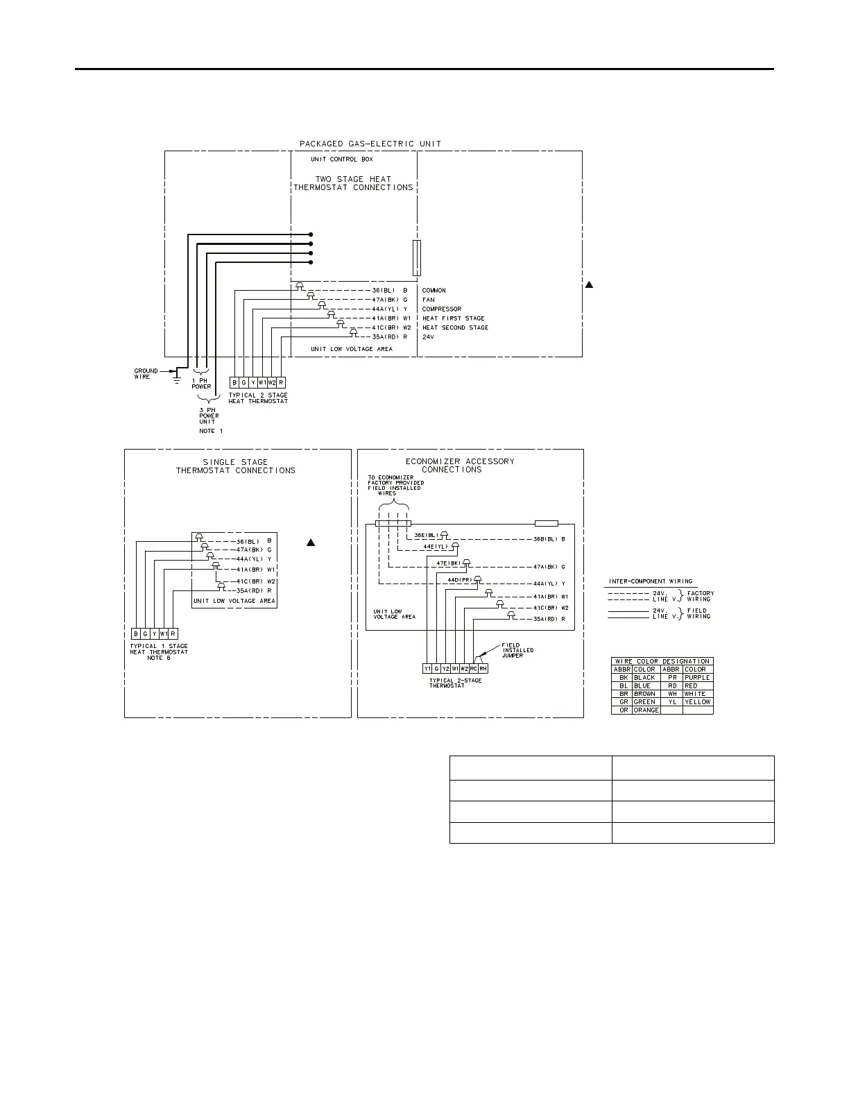
Figure 7. 4YCC4— Field Wiring Diagram
FAN (GR)
(CONSTANT CIRCULATION)
COMMON
CONTACTOR/COMPRESSOR/FAN
HEAT FIRST STAGE (WH)
HEAT SECOND STAGE (WH)
24V
NOTES:
1. FUSED DISCONNECT SIZE, POWER
WIRING AND GROUNDING OF
EQUIPMENT MUST COMPLY WITH
CODES.
2. BE SURE POWER SUPPLY AGREES
WITH EQUIPMENT AND HEATER
NAMEPLATE.
3. LOW VOLTAGE WIRING TO BE
18 AWG MINIMUM CONDUCTOR.
4. SEE UNIT DIAGRAM FOR
ELECTRICAL CONNECTION DETAILS.
5. THE GAS ELECTRIC UNIT WILL
PROVIDE CONSTANT CIRCULATION
REGARDLESS OF COOLING OR
HEATING STATUS WITH A ‘G’ SIGNAL
ONLY FROM THE THERMOSTAT.
6. FOR SINGLE STAGE THERMOSTATS,
JUMPER W1 AND W2 TOGETHER.
SECOND STAGE HEAT WILL BEGIN
10 MINUTES AFTER FIRST STAGE.
DWG. C757192REVA
CCoonnttrrooll WWiirriinngg ((CCllaassss IIII))
Low voltage control wiring should not be run in conduit
with power wiring unless Class 1 wire of proper voltage
rating is used. Route the thermostat cable or equivalent
single leads of No. 18 AWG colored wire from the
thermostat subbase terminals through the rubber
grommet on the unit. See Unit Clearance Graphics for
the control entry (24V Entry) location. Make
connections as shown on the unit wiring diagram.
Do not short thermostat wires since this will damage
the control transformer.
Refer to Table 18, p. 23 for recommended wire sizes
and lengths for installing the unit thermostat. The total
resistance of these low voltage wires must not exceed
one (1) ohm. Any resistance in excess of 1 ohm may
cause the control to malfunction because of the
excessive voltage drop.
Table 18. Thermostat Wire Size and Max. Length
Wire Size
Maximum Length
18 75
16 125
14 200
TThheerrmmoossttaatt HHeeaatt AAnnttiicciippaattoorr
Set the heat anticipator of the thermostat to equal the
amperage draw of the gas valve
IImmppoorrttaanntt:: UUppoonn ccoommpplleettiioonn ooff wwiirriinngg,, cchheecckk aallll
eelleeccttrriiccaall ccoonnnneeccttiioonnss,, iinncclluuddiinngg ffaaccttoorryy
wwiirriinngg wwiitthhiinn tthhee uunniitt..
Make sure all connections are tight. Replace and secure
all electrical box covers and access panels before
leaving the unit or turning on the power to the unit.
UUnniitt IInnssttaallllaattiioonn