20 18-GL07D1-4
2GN SPLIT INSTALLER’S GUIDE
Thermostat Displays
Fault Flash
When using a fault monitor thermostat and SW2-8 is in the
pulsing “L” position (off), the system monitor will enable a user
to view the thermostat and count the fault indicator fl ashes to
determine the lockout condition the unit is experiencing.
When using A/TCONT802 or 803 thermostat and SW2-8 is
in the pulsing “L” position (off), the system monitor will enable
the user to view the thermostat and determine the fault. SW2-
8 in the “on” position will send a constant signal to the fault
indicator in the event of a system lockout condition. The LED
board on the front of the unit will display all lockouts.
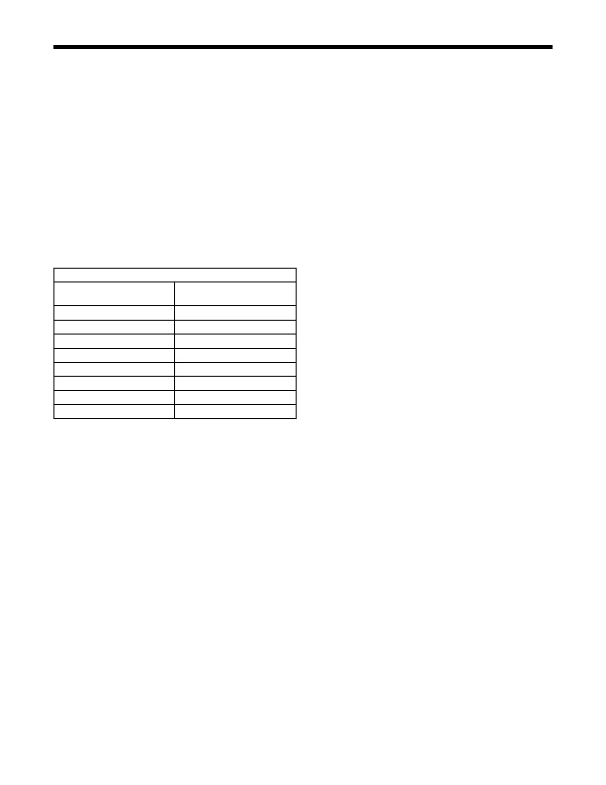
The following table shows the codes that will be displayed
when the System Monitor (L) is connected to the F terminal of
an A / TCON802 or 803 Comfort Control.
A/TCON802 AND 803 THERMOSTATS
THERMOSTAT DISPLAY
LOCKOUT CODE
LOCKOUT DESCRIPTION
2 FLASHES HIGH PRESSURE FAULT
3 FLASHES LOW PRESSURE FAULT
4 FLASHES NOT APPLICABLE
5 FLASHES WATER FAULT LOW
6 FLASHES NOT APPLICABLE
7 FLASHES CONDENSATE FAULT
8 FLASHES VOLTAGE OUT OF RANGE
9 FLASHES RPM FAULT