22-5202-03-3605 (EN) 3
How it works to
keep you comfortable
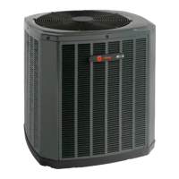
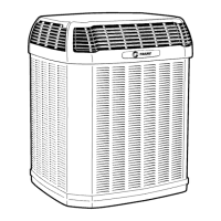
Congratulations on the purchase of your new Trane heat pump.
Your heat pump is designed to work with a matched indoor unit
creating a system that delivers years of dependable service
and performance.
The heat pump is an air conditioning system that both heats and cools. It uses electric
energy to move the heat that already exists.
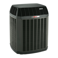
During the winter, the heat pump extracts the heat present in cold winter air and pumps
the heat into your home. (Yes, there’s heat in the air even in the coldest weather.) In
summertime, it functions as a conventional air conditioner, pulling the heat out of your
home and releasing it outside.
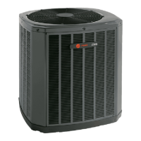
Your heat pump also filters and dehumidifies.
When the Weathertron
®
heat pump circulates air, it also filters it. And since the heat
pump is an air conditioner, it extracts excess moisture from the home, to help control
humidity in muggy summer months.
Acquaint yourself with your new system by spending just a few minutes with this
booklet. Learn about the operation of your system and the small amount of mainte-
nance it takes to keep it operating at peak efficiency.
A heat pump is not a household appli-
ance. It’s a self-contained system that
requires professional maintenance
and repair.
That’s why attempts at “do-it-yourself”
repairs on an in-warranty unit may void
the remainder of your warranty.
Other than performing the simple main-
tenance recommended in this manual,
you should not attempt to make any
adjustments to your heat pump system.
Your dealer will be able to take care of
any questions or problems you may have.
Help ensure top efficiency by cleaning
or replacing the filter monthly.*
When the heat pump circulates and
filters the air in your home, dust and
dirt particles build up on the filter.
Excessive accumulation can block the
airflow, forcing the unit to work harder
to maintain desired temperatures. And
the harder your unit works, the more
energy it uses.
Clean or replace your filter twice a
month during seasons when the unit
runs more often.
When replacing your filter(s), always
use the same size and type that was
originally supplied. Filters are available
from your dealer.
Where disposable filters are used, they
must be replaced every month with the
same size as originally supplied.
How to remove your filter.*
Ask your Trane dealer where the filter
is located in your system and how to
service it.
Just be sure to replace it with the arrows
pointing in the direction of the airflow.
Efficiency can be maintained by
keeping outdoor unit clear of snow,
ice and debris.
Efficient operation of your heat pump
depends on the free flow of air over the
coil. Anything that blocks the airflow,
causes the compressor to work harder to
move the warm air out of your house.
Buildup of snow and ice can restrict
airflow. As soon as possible after accu-
mulation, clean snow from the area
around the heat pump.
To avoid overworking your unit, do not
plant flowers or shrubbery right next to it.
Also, make sure that nothing is stacked
against the sides of the unit or draped
over it.
* Before removing the filter, see the owners manual
furnished with the indoor unit.
Proper maintenance for
maximum efficiency
▲
CAUTION
!
To prevent injury, death, or property damage, read
and follow all instructions and warnings, including
labels shipped with or attached to unit before
operating your new air conditioning system.
▲
WARNING
!
Disconnect all electrical power to the indoor air
handler or furnace before removing access panels
to perform any maintenance. Disconnect power to
both the indoor and outdoor units. NOTE: There
may be more than one electrical disconnect
switch. Electric shock can cause personal injury
or death.
▲
CAUTION
!
Although special care has been taken to minimize
sharp edges in the construction of your unit, be
extremely careful when handling parts or reaching
into the unit.
It heats in winter.
It cools in summer.
 Loading...