Literature Order Number P.I.
File Number
Supersedes
Stocking Location
Trane has a policy of continuous product and product data improvement and it reserves the right to change
design and specifications without notice.
Trane
A business of
American Standard Companies
www.trane.com
Important Service Information
It’s always a good idea to keep records — it will save you time and money. If it’s necessary to have your air conditioner repaired, the
serviceman will want to know if your unit is still under Warranty. Take a few minutes to record the following information here:
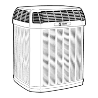
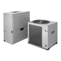
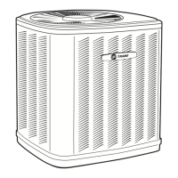
Outdoor Model Number ___________________________________________________________________________________
Indoor Model Number ____________________________________________________________________________________
Thermostat Model Number ________________________________________________________________________________
Date of Purchase ________________________________________________________________________________________
Dealer ________________________________________________________________________________________________
Service Information
Call your installing dealer if the unit is inoperative. Before you call, always check the following to be sure service is required:
a. Be sure the main switch that supplies power to the unit is in the ON position.
b. Replace any burned-out fuses or reset circuit breakers.
c. Be sure the thermostat is properly set.
Service Phone __________________________________________________________________________________________
2TWB-SVU01A-EN
SV-UN-2TWB-SSP-SVU-01A-EN-605
2TWB0-UM-2
PI Louisville & Webb/Mason-Houston
 Loading...