Page 19
Installer’s Guide
Air Filter Installation
The packaged unit requires an air filter. The unit does not come
with a factory installed filter rack in it, however, two filter frame ac-
cessories are offered that will allow the installation of a filter within
the unit, BAYFLTR101 & BAYFLTR201. Otherwise a field supplied
filter rack must be installed by the installer in the return duct work.
Refer to Table 5 to determine filter sizes for field supplied filter racks.
*Filters must be installed in the return air system. The above square
footages are based on 300 F.P.M. face velocity. If permanent filters are
used, size per mfg. Recommendation with clear resistance of 0.05" W.C.
High Altitude Installation
Unit nameplate ratings are based on equipment operation from
sea level to 2000 feet elevation above sea level. No orifice changes
required for high altitude installation, please refer to below chart for
rating information.
Table 4. High Altitude Derate Chart
Table 5. Filter Sizes (field supplied filter rack)
Electrical Connections
Electrical wiring and grounding must be installed in accordance
with local codes or, in the absence of local codes, with the National
Electrical Code ANSI/NFPA 70, Latest Revision.
Electrical Wiring
NOTE: This unit is factory wired for 230V. See wiring dia-
gram in SERVICE FACTS for 208V conversion.
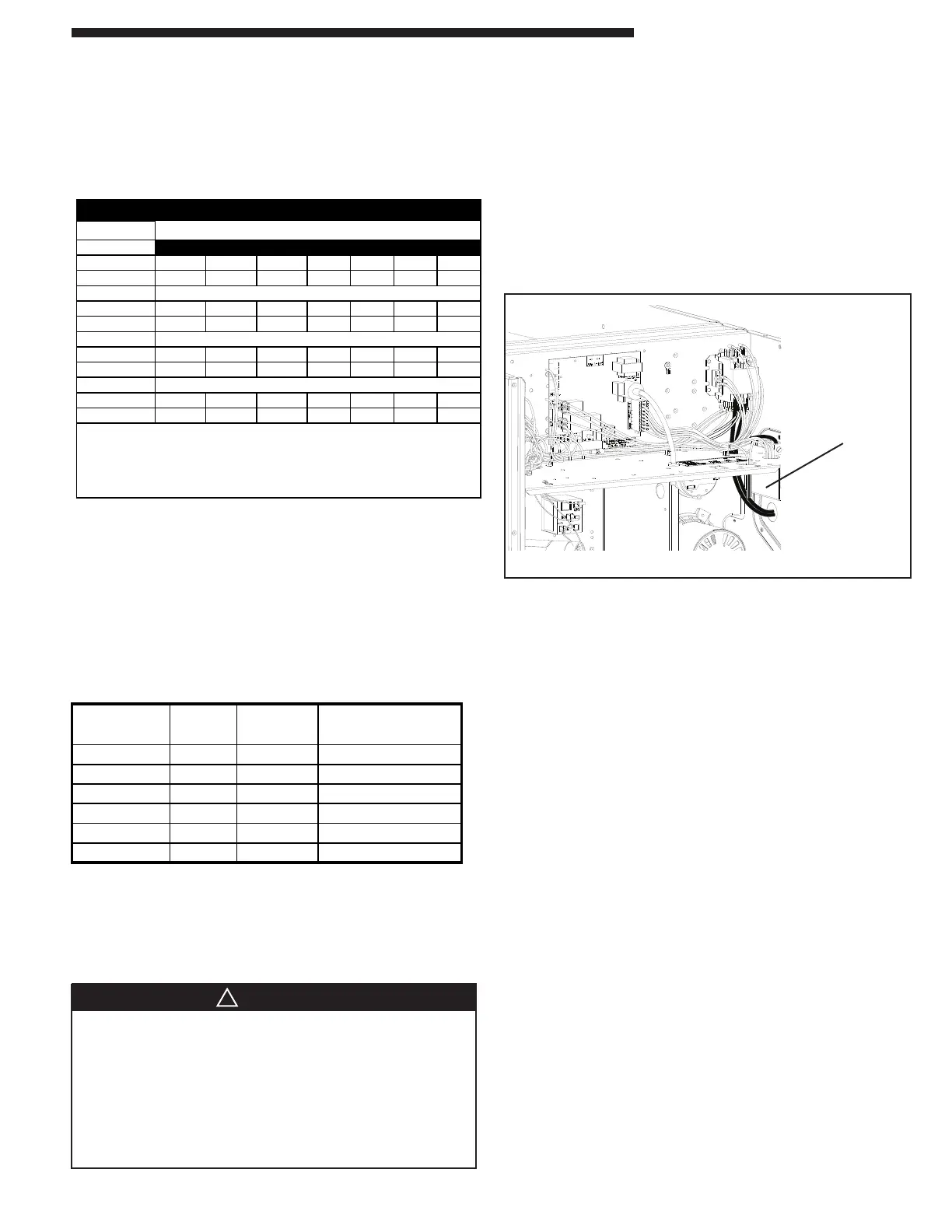
Figure 19. Power Wiring
NOTE: For branch circuit wiring (main power supply to unit
disconnect), determine wire size for the length of run using the
circuit ampacity found on the unit nameplate and the N.E.C.
For more than 3 conductors in a raceway or cable, see the
N.E.C. for derating the ampacity of each conductor.
Run power supply
Lines through
weather-tight con-
duit and secure
to unit with strain
relief
Unit Input
120k 2001 3000 4000 5000 6000 7000 8000
High stage
117000 108700 100400 92000 90700 89400 88800
Low stage
87700 81500 75300 69000 68000 67000 66600
96k
High stage
93600 87000 80300 73600 72600 71500 71000
Low stage
70200 65200 60200 55200 54400 53600 53300
75k
High stage
73100 67900 62700 57500 56700 55900 55500
Low stage
54800 51000 47100 43100 42500 41900 41600
64k
High stage
62400 58000 53500 49100 48400 47700 47300
Low stage
46800 43500 40200 36800 36300 35700 35500
For LP installations. Models that require #49 orifices, for
altitudes from 7000 - 8000' orifices must be changed to #50.
HIGH ALTITUDE DERATE CHART NAT.
Altitude (In Feet)
Inputs shown are with factory orifices @ 3.5"WC (High Fire)
1.8"WC (Low Fire)
Natural Gas heating value of 950 btu/cuft.
Electrical Power
It is important that proper electrical power be available for the unit.
Voltage variation should remain within the limits found on the unit
nameplate.
Disconnect Switch
Provide an approved weatherproof disconnect within close proxim-
ity and within sight of the unit. If disconnect must be mounted
to the cabinet, the location shown in Figure 21 should be the only
one considered.
Over Current Protection
The branch circuit feeding the unit must be protected as shown on
the unit nameplate.
Power Wiring
The power supply lines must be run in weather-tight conduit to the
disconnect and into the side of the unit control box. Provide strain
relief for all conduit with suitable connectors.
Provide flexible conduit supports whenever vibration transmission
may cause a noise problem within the building structure.
1. Remove the CONTROL/HEAT access panel. Pass the power
wires through the Power Entry hole in the end of the unit.
See Figure 19.
2. Connect the high voltage wires to the appropriate contactor lug
terminals. Single phase units use a two (2) pole contactor
and three phase units use two (2) pole contactor and a Blue
lead wire. Connect the ground to the ground lug on the chas-
sis. See Figure 20. Be sure all connections are tight.
GROUNDING: THE UNIT MUST BE ELECTRICALLY
GROUNDED IN ACCORDANCE WITH LOCAL CODES OR
THE NATIONAL ELECTRIC CODE.
NOTE: Unit must be grounded for ignitor to operate properly.
Gas pipe to unit is not an adequate ground. Ground the unit
internally as provided.
HAZARDOUS VOLTAGE, MOVING PARTS, AND GAS
Bodily injury can result from high voltage electrical compo-
nents, fast moving fans, and combustible gas. For protection
from these inherent hazards during installation and service,
the electrical supply must be disconnected and the main
gas valve must be turned off. If operating checks must be
performed with the unit operating, it is the technician's re-
sponsibility to recognize these hazards and proceed safely.
NOMINAL FILTER
CFM SIZE(Sq Ft)
4*CY4024 800 2.67 0.08
4*CY4030 1000 3.33 0.08
4*CY4036 1200 4 0.08
4*CY4042 1400 4.67 0.08
4*CY4048 1600 5.33 0.08
4*CY4060 2000 6.67 0.08
UNIT
FILTER
RESISTANCE ("W.C.)