18-AC76D1-5 15
Comfort Control
Air Handler
Air Conditioner
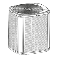
Neatly bundle all low voltage
wires behind the service
valve cover as shown.
Field wiring
Yellow
Blue
Red
Yellow
Green
White
Blue
B
B - Blue
W
G
Y1
Y2
Y1 - Yellow
R
O
O
R
B
YI
W1
YO
Y2
DH/BK
G
W2
W3
(In)
(Out)
Red
Yellow
Green
White
Blue
Yellow
Green
White
Blue
B
B - Blue
Blue
W
G
Y
Y - Yellow
Yellow
R
Red
O
Orange
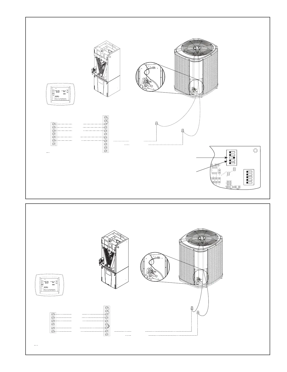
Comfort Control
Air Handler
Field wiring
Air Conditioner
O **
R **
B
YI (In)
W1
YO (Out)
G
W2
W3
Neatly bundle all low voltage
wires behind the service
valve cover as shown.
* For multiple stages of 1.
electric heat, jumper W1,
W2, and W3 together if
comfort control has only
one stage of heat.
** R to 2. O jumper must
be in place as shown for
cooling only, non-heat
pump systems for proper
operation.
Yi and Yo connections 3.
must be made as shown
for freeze protection and
internally mounted con-
densate overflow circuits
to work properly.
Internally mounted con-4.
densate switch is optional
and must be ordered
separately.
If 3rd party condensate 5.
overflow switches are
installed, they should be
wired in series between
YO and Y to the outdoor
unit.
GAM5 Air Handler
Hook-up Diagram
*AM7 Air Handler
Hook-up Diagram
1
1
1 2 3 4 5
1 2 3 4 5
HP
2(Comp ressor)
2(Stages)
AC (System)
}
OUTDOOR
Capacity (Tons)
OUTDOOR
}
Torque
CFM/Ton
Cool OffDelay
}
INDOOR
CFM
+12V
R13
R14
R1
R4
1
U1
RNET 1
S1
on
on
S2
RNET 2
R
6
C22
C19
C
15
C
12
C18
C21
C10
D9
L1
R22
Must configure to
“ON” for AC Units.
Must configure to “OFF” for
single-stage compressors.
Control Board
 Loading...