10 MS-SVN052E-EN
Unit Installation
IMPORTANT NOTE:
These instructions are intended to provide a method of installation of the unit to the concrete base
in order to establish a protective procedure in cases of strong winds. It is recommended to verify
local codes for the application of methods and protocols for secure setting of the unit.
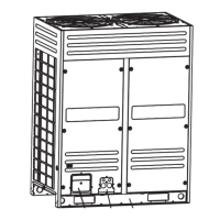
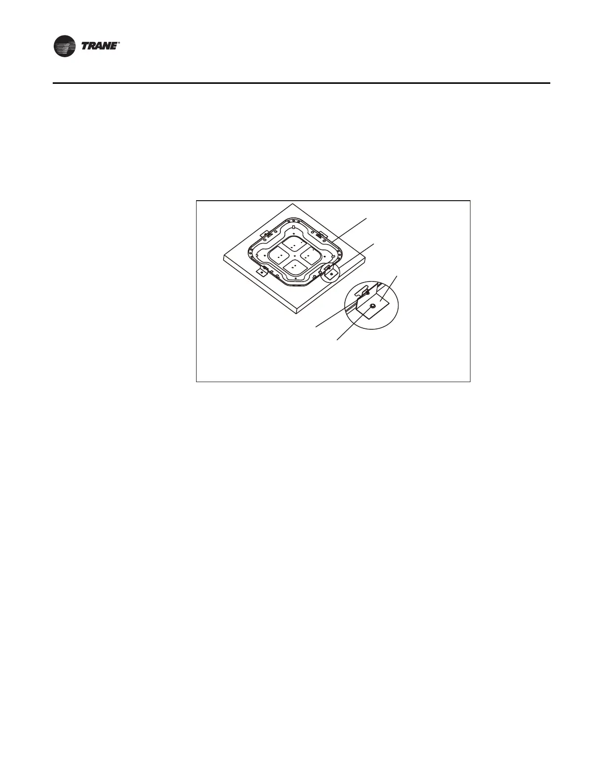
Figure 4. Preferred Method for Unit Setting
Cautions to be Observed During Installation of Refrigerant Lines
1. Install lines with the least amount of curves possible. Avoid damaging line couplings or line
curves. Use clean and hard drawn copper tubing at points where it will not be necessary to
apply multiple curves around obstructions. When it is necessary to use soft copper, it should
be carefully applied avoiding sharp curves that may provoke any type of restriction.
2. Install lines avoiding any obstructions to the coil, to the air handling components o to the filter.
3. Take special care in the application of insulation to refrigerant lines in order to minimize the
transmission of sound to the structure.
4. When applying insulation material to the suction line, refrigerant lines should be supported as
illustrated in Figure 5. DO NOT allow any friction contact between metal piping.
5. Use PVC piping as conduit in all underground installations. See Figure 6. Underground lines
should be kept as short as possible in order to minimize the accumulation of liquid refrigerant
in the suction line during extended system shutdown periods.
6. In an effort to reduce vibrations and to retain some degree of flexibility, place a type of sealant
material like permagum or similar around refrigerant lines that must be directed through walls.
See Detail B
#7 X 3/8” drill screws
(Not to exceed 3/8” in length)
´ȋ´ZDVKHUDQGKH[VFUHZVIRUFRQFUHWH
(Pilot hole required 3/16”. Pilot hole should be 1/4” deeper than the space
occupied by the bracket).
DETAIL B
Brackets:
´ZLGH´WKLFN
height as required.
$YDLODEOHIURPYHQGRU
RULQWKHILHOG
6HHGLPHQVLRQVLQ)LJ
 Loading...