22
18-EB41D1-1B-EN
EElleeccttrriiccaall PPoowweerr
It is important that proper electrical power be available
for the unit. Voltage variation should remain within the
limits stamped on the unit nameplate.
DDiissccoonnnneecctt SSwwiittcchh
Provide an approved weatherproof disconnect within
close proximity and wwiitthhiinn ssiigghhtt ooff tthhee uunniitt. If
disconnect must be mounted to the cabinet, the
location shown in Table 15, p. 22 should be the only
one considered.
OOvveerr CCuurrrreenntt PPrrootteeccttiioonn
The branch circuit feeding the unit must be protected
as shown on the unit's rating plate.
PPoowweerr WWiirriinngg
The power supply lines must be run in weather-tight
conduit to the disconnect and into the side of the unit
control box. Provide strain relief for all conduit with
suitable connectors.
Provide flexible conduit supports whenever vibration
transmission may cause a noise problem within the
building structure.
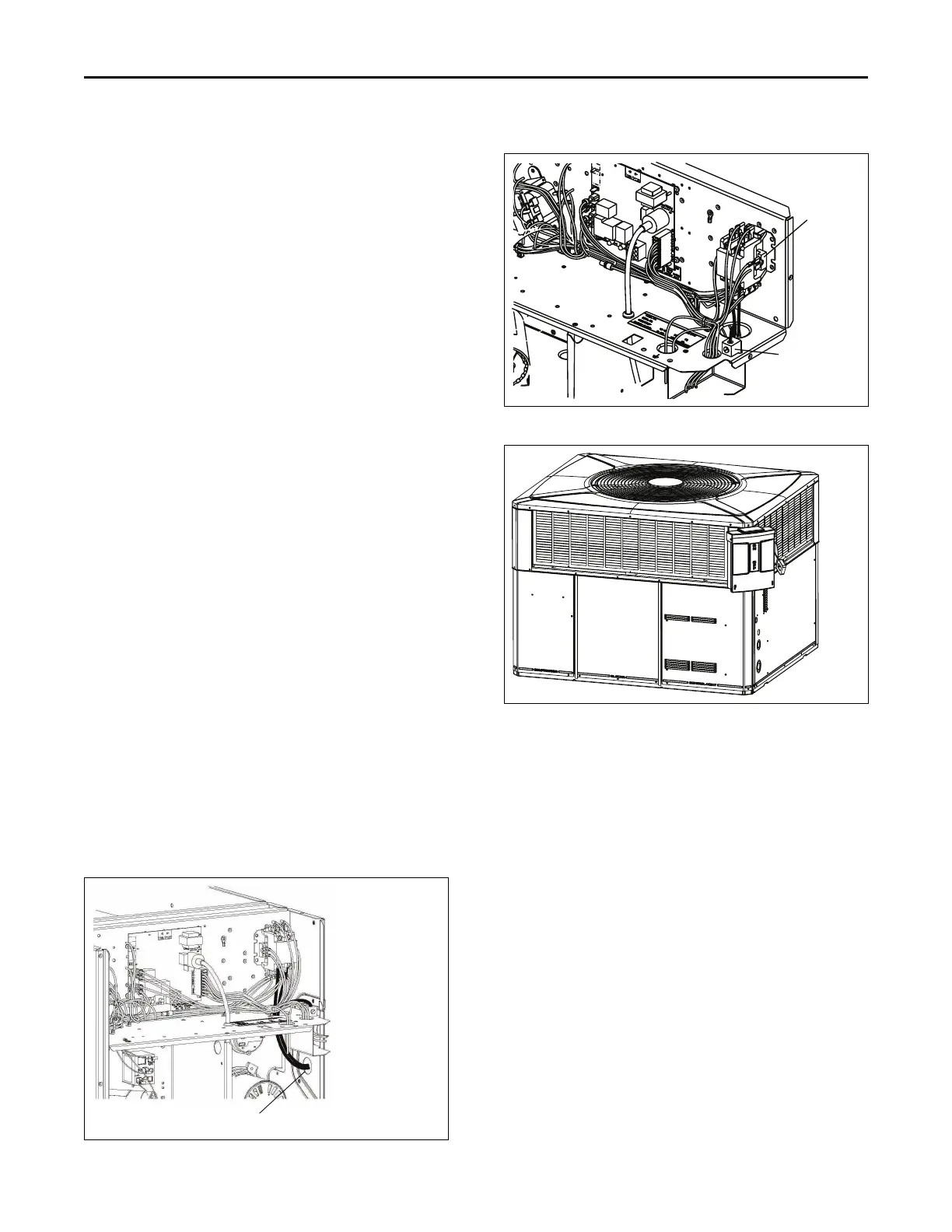
1. Remove the Control/Heat access panel. Pass the
power wires through the Power Entry hole in the
end of the unit. See Table 13, p. 22.
2. Connect the high voltage wires to the appropriate
contactor terminals. Single phase units use a two
(2) pole contactor and three phase units use three
(3) pole contactor. Connect the ground to the
ground lug on the chassis. See Table 14, p. 22.
Ensure all connections are tight.
GGRROOUUNNDDIINNGG:: TTHHEE UUNNIITT MMUUSSTT BBEE EELLEECCTTRRIICCAALLLLYY
GGRROOUUNNDDEEDD IINN AACCCCOORRDDAANNCCEE WWIITTHH LLOOCCAALL CCOODDEESS
OORR TTHHEE NNAATTIIOONNAALL EELLEECCTTRRIICC CCOODDEE..
NNoottee:: Unit must be grounded for ignitor to operate
properly. Gas pipe to unit is not an adequate
ground. Ground the unit internally as provided.
See, Field Wiring Diagram for location in Figure
7, p. 23.
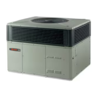
Table 13. Power Wiring
Run power supply lines through weather-tight
conduit and secure to unit with strain relief.
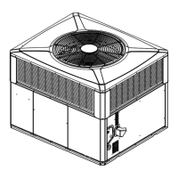
Table 14. Power Connections
Table 15. Mounted Disconnect Location
CCoonnttrrooll WWiirriinngg ((CCllaassss IIII))
Low voltage control wiring should not be run in conduit
with power wiring unless Class 1 wire of proper voltage
rating is used. Route the thermostat cable or equivalent
single leads of No. 18 AWG colored wire from the
thermostat subbase terminals through the rubber
grommet on the unit. See Unit Clearance Graphics for
the control entry (24V Entry) location. Make
connections as shown on the unit wiring diagram.
Do not short thermostat wires since this will damage
the control transformer.
Refer to Table 16, p. 23 for recommended wire sizes
and lengths for installing the unit thermostat. The total
resistance of these low voltage wires must not exceed
one (1) ohm. Any resistance in excess of 1 ohm may
cause the control to malfunction because of the
excessive voltage drop.
UUnniitt IInnssttaallllaattiioonn
 Loading...