13 GAM5-SF-1P-EN
WIRING DATA
GAM5B0C60M51SB, GAM5B0C60M51EA
Heater
Model
No.
No.
of
Circuits
240 VOLT 208 VOLT
Capacity
Heater
Amps
per
Circuit
Minimum
Circuit
Ampacity
Maximum
Overload
Protection
Capacity
Heater
Amps
per
Circuit
Minimum
Circuit
Ampacity
Maximum
Overload
Protec-
tion
kW BTUH kW BTUH
No Heater - - - 7.6* 10 15 - - 7.6* 10 15
BAYEAAC04BK1
BAYEAAC04LG1
1 3.84 13100 16.0 30 30 2.88 9800 13.8 27 30
BAYEAAC05BK1
BAYEAAC05LG1
1 4.80 16400 20.0 35 35 3.60 12300 17.3 31 35
BAYEAAC08BK1
BAYEAAC08LG1
1 7.68 26200 32.0 50 50 5.76 19700 27.7 44 45
BAYEAAC10BK1
BAYEAAC10LG1
1 9.60 32800 40.0 60 60 7.20 24600 34.6 53 60
BAYEAAC10LG3 1-3 PH 9.60 32800 23.1 37 40 7.20 24600 20.0 34 35
BAYEABC15LG3 1-3 PH 14.40 49200 34.6 52 60 10.80 36900 30.0 46 50
BAYEABC15BK1 - Circuit 1①
2
9.60 32800 40 60 60 7.20 24600 34.6 53 60
BAYEABC15BK1 - Circuit 2 4.80 16400 20 25 25 3.60 12300 17.3 22 25
BAYEABC20BK1 - Circuit 1①
2
9.60 32800 40 60 60 7.20 24600 34.6 53 60
BAYEABC20BK1 - Circuit 2 9.60 32800 40 50 50 7.20 24600 34.6 43 45
BAYEACC25BK1②③- Circuit 1①
3
9.60 32800 40 60 60 7.20 24600 34.6 53 60
BAYEACC25BK1 - Circuit 2 9.60 32800 40 50 50 7.20 24600 34.6 43 45
BAYEACC25BK1 - Circuit 3 4.80 16400 20 25 25 3.60 12300 17.3 22 25
Note: * Motor Amps
①MCA and MOP for circuit 1 contains the motor amps
② If the air handler is applied in downflow or horizontal configurations, the airflow should not exceed 2000 CFM. Airflow above 2000 CFM could
result in water blow-off.
③ Tap 5 can be used but only when the external static pressure is .6" or above.
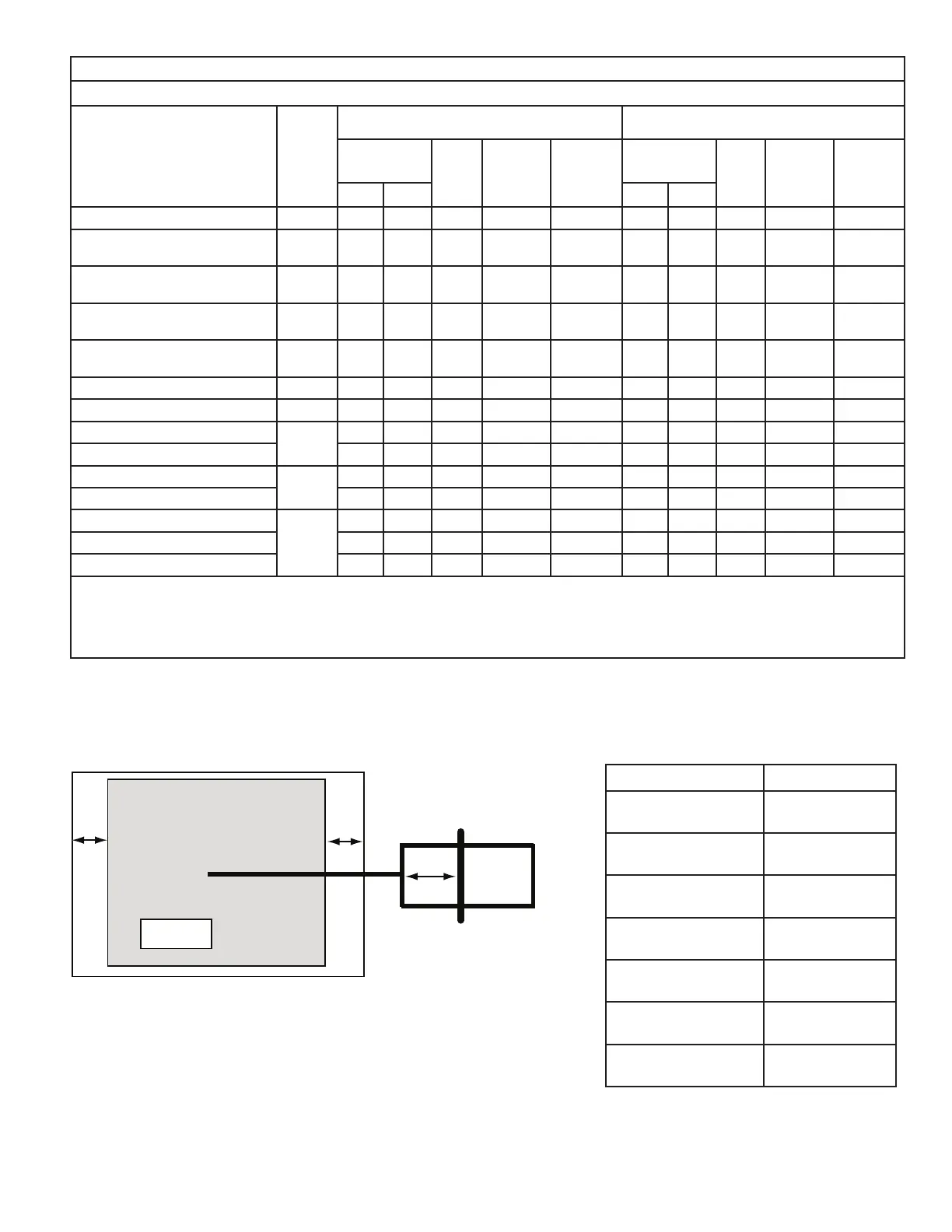
DISTANCE FROM BELLY BAND TO SHAFT FACE OF MOTOR FOR MINIMUM VIBRATION
WHEEL
BLOWER HOUSING
BELLY BAND
MOTOR
A
A is determined per chart
Wheel is centered in
Blower Housing
MODEL DIM "A"
GAM5B0A18M11SB
GAM5B0A18M11EA
1-1/8
GAM5B0A24M21SB
GAM5B0A24M21EA
1-1/8
GAM5B0B30M21SB
GAM5B0B30M21EA
1-1/8
GAM5B0B36M31SB
GAM5B0B36M31EA
1-1/2
GAM5B0C42M31SB
GAM5B0C42M31EA
1-1/2
GAM5B0C48M41SB
GAM5B0C48M41EA
2-1/4
GAM5B0C60M51SB
GAM5B0C60M51EA
2-1/4
 Loading...


