3 GAM5-SF-1P-EN
Note: Heating and cooling speeds are the same, factory
set at Speed Tap #4.
Note: A “G” only signal from the comfort control will run
the blower at a lower speed, factory set at Speed Tap #1.
See the Sequence of Operation for additional information.
Note: Speed Tap 1 is NOT used for two stage systems.
Two stage systems will require an airflow adjustment.
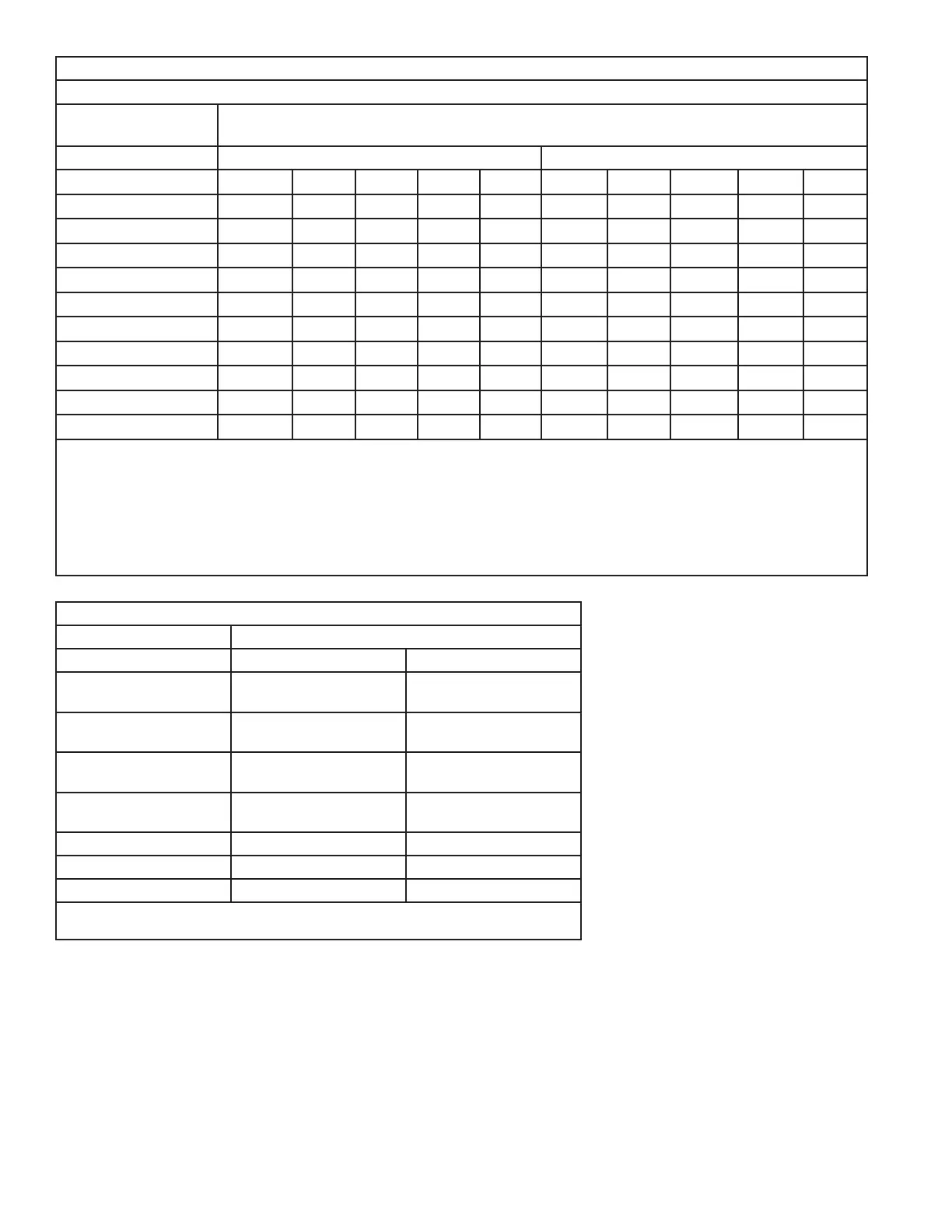
AIRFLOW PERFORMANCE
GAM5B0A18M11SB, GAM5B0A18M11EA
EXTERNAL STATIC
(in w.g)
AIRFLOW (CFM)
Speed Taps - 230 VOLTS Speed Taps - 208 VOLTS
5 4 † 3 2 1 5 4 † 3 2 1
0 1081 977 930 862 556 1078 974 927 858 553
0.1 1044 922 850 806 379 1038 916 844 800 373
0.2 995 880 787 702 202 987 871 778 693 193
0.3 956 830 738 621 - 944 819 727 610 -
0.4 914 788 692 562 - 900 774 677 548 -
0.5 872 749 646 502 - 855 732 629 485 -
0.6 838 707 590 445 - 819 687 570 425 -
0.7 802 650 528 389 - 779 628 505 367 -
0.8 755 598 478 327 - 730 573 453 302 -
0.9 708 539 420 - - 680 512 392 - -
NOTES:
1. Values are with wet coil and without filters.
2. Contact your particular filter manufacturer for pressure drop data.
3. Electric heater pressure drop is negligible and is included within the airflow data.
4. Tap 1 is an continuous fan speed tap for single stage systems. Airflow adjustment is required for 2 stage systems.
See Airflow adjustment section.
5. † Factory Setting
GAM5B0A18M11SB, GAM5B0A18M11EA MINIMUM HEATER AIRFLOW CFM
Heater Minimum Air Speed Tap
Without Heat Pump With Heat Pump
BAYEAAC04BK1
BAYEAAC04LG1
Tap 3 Tap 4
BAYEAAC05BK1
BAYEAAC05LG1
Tap 3 Tap 4
BAYEAAC08BK1
BAYEAAC08LG1
Tap 3 Tap 4
BAYEAAC10BK1
BAYEAAC10LG1
Tap 3 ① Tap 5 ①
BAYEAAC10LG3 Tap 5 Tap 5 ②
BAYEABC15BK1 - -
BAYEABC20BK1 - -
① Heater not qualified for downflow installations
② Approved for 240 V only