GAM5-SF-1P-EN 4
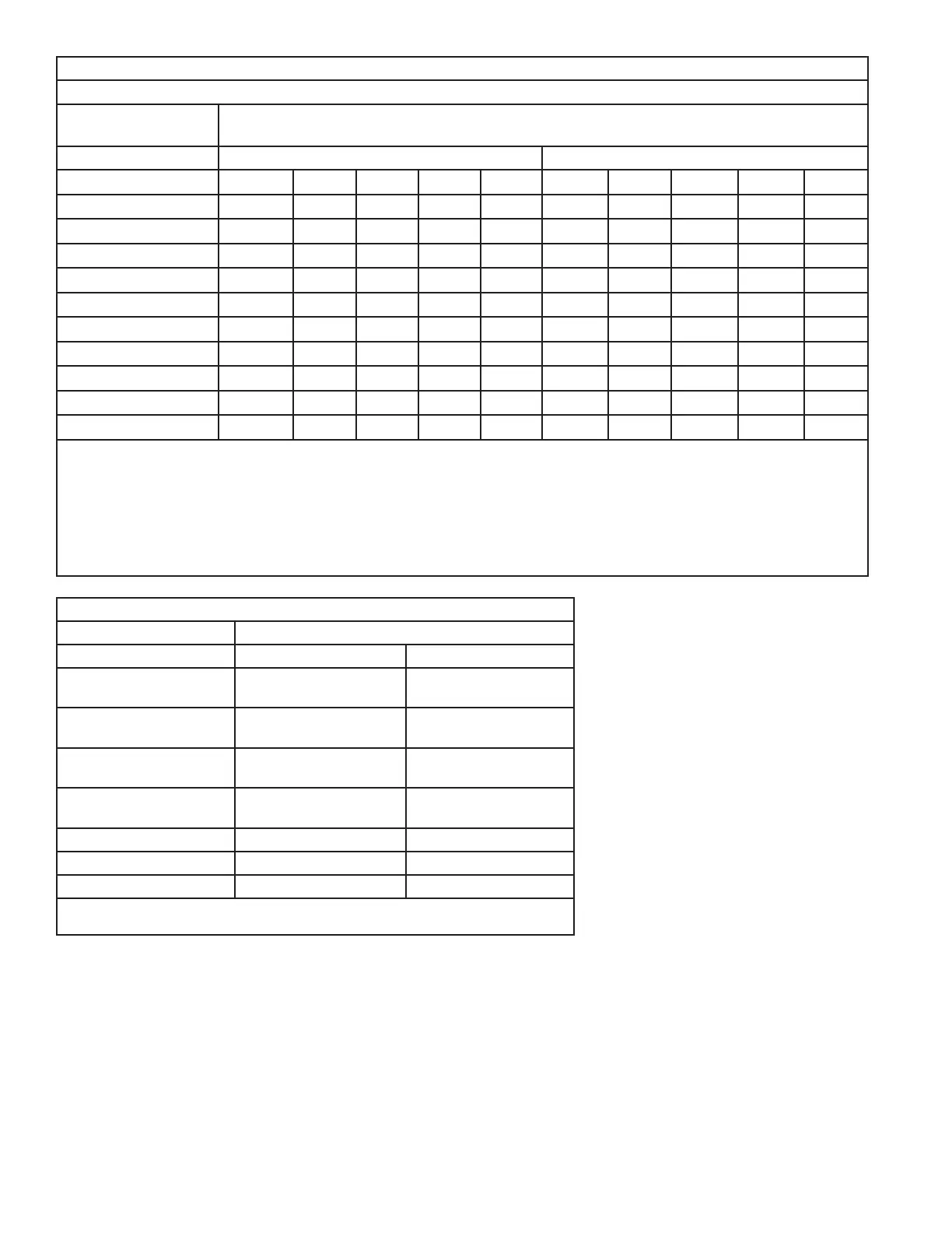
AIRFLOW PERFORMANCE
GAM5B0A24M21SB, GAM5B0A24M21EA
EXTERNAL STATIC
(in w.g)
AIRFLOW (CFM)
Speed Taps - 230 VOLTS Speed Taps - 208 VOLTS
5 4 † 3 2 1 5 4 † 3 2 1
0 1081 977 937 928 579 1078 974 933 925 576
0.1 1044 922 868 844 418 1038 916 863 838 412
0.2 995 880 817 777 306 987 871 808 768 298
0.3 956 830 767 729 - 944 819 756 717 -
0.4 914 788 719 682 - 900 774 705 668 -
0.5 872 749 680 635 - 855 732 663 618 -
0.6 838 707 628 577 - 819 687 609 557 -
0.7 802 650 566 515 - 779 628 544 492 -
0.8 755 598 511 467 - 730 573 486 442 -
0.9 708 539 460 407 - 680 512 432 - -
NOTES:
1. Values are with wet coil and without filters.
2. Contact your particular filter manufacturer for pressure drop data.
3. Electric heater pressure drop is negligible and is included within the airflow data.
4. Tap 1 is an continuous fan speed tap for single stage systems. Airflow adjustment is required for 2 stage systems.
See Airflow adjustment section.
5. † Factory Setting
Note: Heating and cooling speeds are the same, factory
set at Speed Tap #4.
Note: A “G” only signal from the comfort control will run the
blower at a lower speed, factory set at Speed Tap #1. See
the Sequence of Operation for additional information.
Note: Speed Tap 1 is NOT used for two stage systems.
Two stage systems will require an airflow adjustment.
GAM5B0A24M21SB, GAM5B0A24M21EA MINIMUM HEATER AIRFLOW CFM
Heater Minimum Air Speed Tap
Without HP With HP
BAYEAAC04BK1
BAYEAAC04LG1
Tap 3 Tap 4
BAYEAAC05BK1
BAYEAAC05LG1
Tap 3 Tap 4
BAYEAAC08BK1
BAYEAAC08LG1
Tap 3 Tap 4
BAYEAAC10BK1
BAYEAAC10LG1
Tap 3 ① Tap 5 ①
BAYEAAC10LG3 Tap 5 Tap 5 ②
BAYEABC15BK1 - -
BAYEABC20BK1 - -
① Heater not qualified for downflow installations
② Approved for 240 V only