18-AC130D1-1B-EN 3
Table 2.1
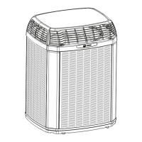
Unit Dimensions and Weight
Models H x D x W (in) Weight* (lb)
5TTX5018A
42 x 30 x 33 193
5TTX5024A 38 x 30 x 33 165
5TTX5030A 42 x 30 x 33 195
5TTX5036A 38 x 30 x 33 165
5TTX5042A 44 x 34 x 37 221
5TTX5048A 52 x 34 x 37 261
5TTX5060A 52 x 34 x 37 261
* Weight values are estimated.
Section 2. Unit Location Considerations
2.1 Unit Dimensions and Weight
When mounting the outdoor unit on a roof, be sure
the roof will support the unit’s weight.
Properly selected isolation is recommended to
alleviate sound or vibration transmission to the
building structure.
D
H
W
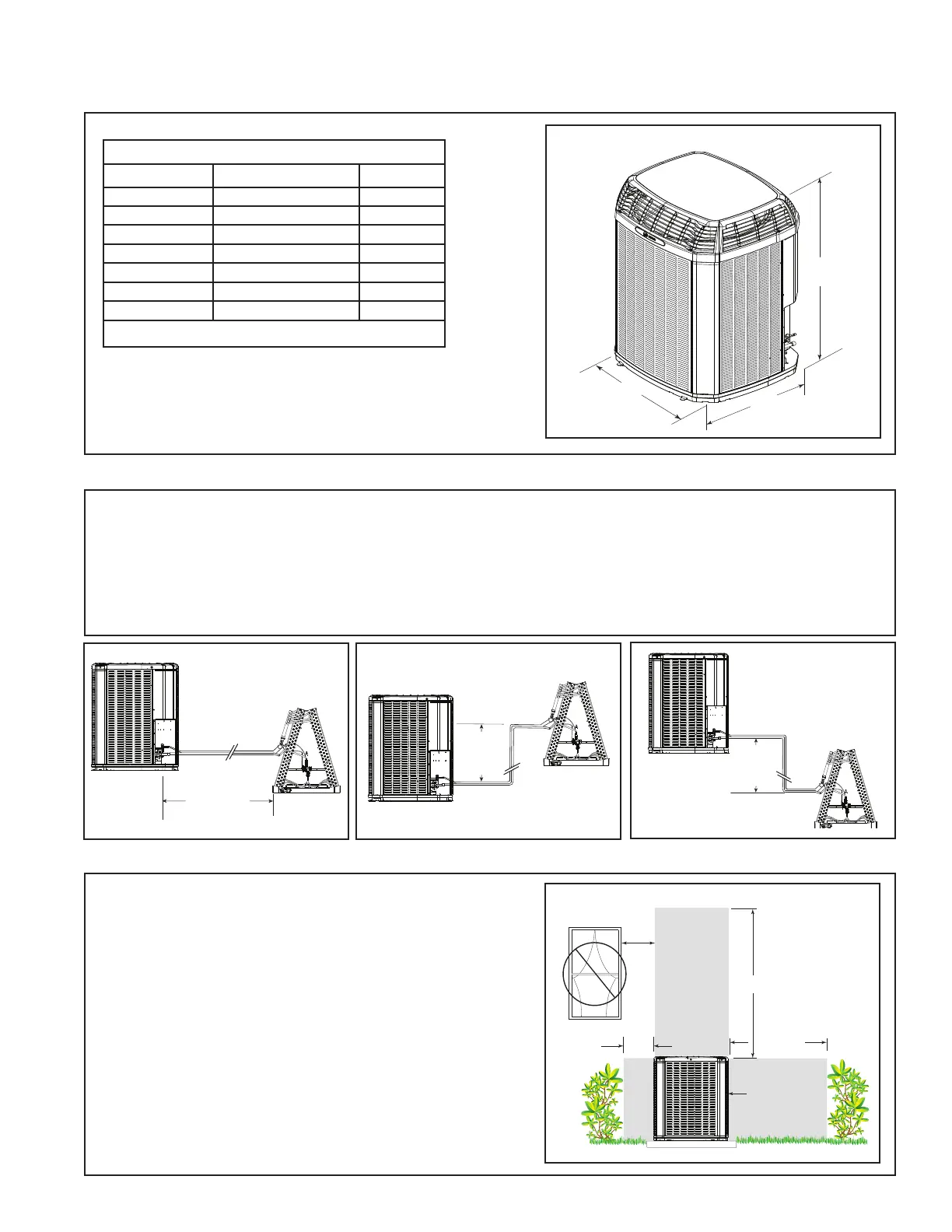
2.2 Refrigerant Piping Limits
1. The maximum TOTAL length of refrigerant lines from outdoor to indoor unit should NOT exceed 150 feet
(including lift).
2. The maximum vertical change should not exceed 50 feet.
3. Service valve connection diameters are shown in Table 5.1.
Note: For other line lengths, refer to Refrigerant Piping Application Guide, SS-APG006-EN or Refrigerant Piping
Software Program, 32-3312-03 (or latest revision).
Standard
Line Set
150’ Max
TOTAL Line Length
50’
Max
Vertical
Change
50’
Max
Vertical
Change
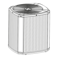
Min. 12” to
Shrubbery
Avoid Install
Near Bedrooms
Min 5’ Unrestricted
Access Panel
Min 3’
Unrestricted
2.3 Suggested Locations for Best Reliability
Ensure the top discharge area is unrestricted for at
least five (5) feet above the unit.
Three (3) feet clearance must be provided in front of
the control box (access panels) and any other side
requiring service.
Do not locate close to bedrooms as operational sounds
may be objectionable.
Position the outdoor unit a minimum of 12” from any
wall or surrounding shrubbery to ensure adequate
airflow.
Outdoor unit location must be far enough away from
any structure to prevent excess roof runoff water from
pouring directly on the unit.
Please reference Indoor Unit Installer’s Guide for
correct specifications on indoor unit install.