18-GF14D1-1C-EN
17
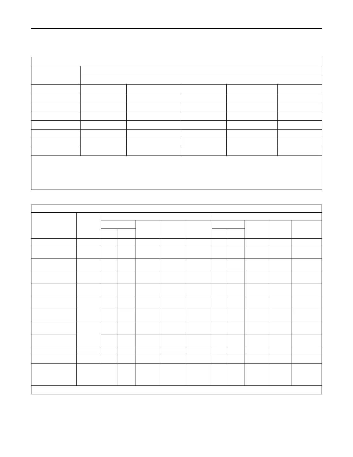
Table 8. Air Flow Performance
A4AH6E43A1C30B
EXTERNAL STATIC
(in w.g)
AIRFLOW
Speed Taps — 208 – 230 VOLTS
High Med-High
Med † Med-Low Low
0.1 1491.6 1418.1 1302.5 1267.8 1140.4
0.2 1459.7 1384.7 1266.3 1230.1 1096.4
0.3 1425.8 1349.2 1227.8 1189.7 1050.3
0.4 1389.8 1311.3 1187.0 1146.8 1002.1
0.5 1351.6 1271.3 1144.0 1101.4 951.7
0.6 1311.4 1229.0 1098.7 1053.3 899.3
0.7 1269.1 1184.4 1051.1 1002.7 844.7
1. Values are with wet coil, no filter, and no heaters
2. CFM Correction for dry coil = Add 3%
3. † = Factory Setting
4. In downflow applications, airflow must not exceed 1600 cfm due to condensate blowoff.
5. Low = Tap 1, Med-Low = Tap 2, Med = Tap 3, Med-High= Tap 4, High = Tap 5
Table 9. Electrical Data
A4AH6E43A1C30B
Heater Model No.
No. of
Circuits/
Phases
240 Volt 208 Volt
Capacity
Heater
Amps per
Circuit
Minimum
Circuit
Ampacity
Maximum
Overload
Protection
Capacity
Heater
Amps per
Circuit
Minimum
Circuit
Ampacity
Maximum
Overload
Protection
kW BTUH kW BTUH
No Heater 4.1 * 8 15 4.1 * 8 15
BAYHTR1504BRK
BAYHTR1504LUG
1/1
3.8 13100 16.0 28 30 2.9 9800 13.8 25 25
BAYHTR1505BRK
BAYHTR1505LUG
1/1
4.8 16400 20.0 33 35 3.6 12300 17.3 29 30
BAYHTR1508BRK
BAYHTR1508LUG
1/1
7.7 26200 32.0 48 50 5.8 19700 27.7 42 45
BAYHTR1510BRK
BAYHTR1510LUG
1/1
9.6 32800 40.0 58 60 7.2 24600 34.6 51 60
BAYHTR1517BRK-
Circuit 1
(a)
2/1
9.6 32800 40.0 58 60 7.2 24600 34.6 51 60
BAYHTR1517BRK-
Circuit 2
4.8 16400 20.0 25 25 3.6 12300 17.3 22 25
BAYHTR1523BRK-
Circuit 1
2/1
9.6 32800 40.0 58 60 7.2 24600 34.6 51 60
BAYHTR1523BRK-
Circuit 2
9.6 32800 40.0 50 50 7.2 24600 34.6 43 45
BAYHTR3510LUG
1/3
9.6 32800 23.1 36 40 7.2 24600 20.0 32 35
BAYHTR3517LUG
1/3
14.4 49100 34.6 50 50 10.8 36900 30.0 44 45
BAYHTR1517BRK
with single circuit
power source kit
BAYSPEKT201A
1/1
14.4 49200 60.0 83 90 10.8 36900 51.9 73 80
* = Motor Amps
(a)
MCA and MOP for circuit 1 contains the motor amps.
PPeerrffoorrmmaannccee aanndd EElleeccttrriiccaall DDaattaa
 Loading...
