18
18-GF14D1-1C-EN
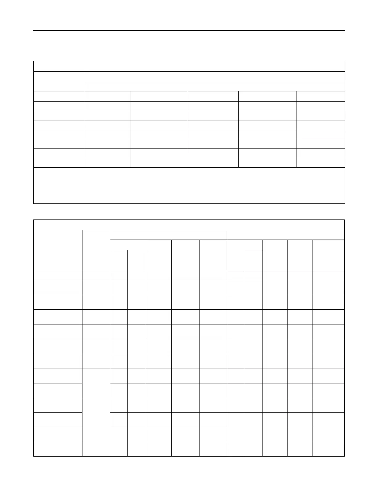
Table 10. Air Flow Performance
A4AH6E49A1C30B, A4AH6E61A1C30B
EXTERNAL STATIC
(in w.g)
AIRFLOW
Speed Taps — 208 – 230 VOLTS
High Med-High
Med † Med-Low Low
0.1 1954.3 1790.6 1578.2 1546.0 1296.6
0.2 1908.4 1733.6 1520.4 1487.4 1223.5
0.3 1860.4 1676.3 1461.2 1427.0 1150.5
0.4 1810.3 1618.9 1400.5 1364.8 1077.4
0.5 1758.1 1561.2 1338.5 1300.6 1004.3
0.6 1703.8 1503.2 1275.1 1234.5 931.3
0.7 1647.4 1445.1 1210.2 1166.6 858.2
1. Values are with wet coil, no filter, and no heaters
2. CFM Correction for dry coil = Add 3%
3. † = Factory Setting
4. In downflow applications, airflow must not exceed 1600 cfm due to condensate blowoff.
5. Low = Tap 1, Med-Low = Tap 2, Med = Tap 3, Med-High= Tap 4, High = Tap 5
Table 11. Electrical Data
A4AH6E49A1C30B, A4AH6E61A1C30B
Heater Model No.
No. of
Circuits/
Phases
240 Volt 208 Volt
Capacity
Heater
Amps
per
Circuit
Minimum
Circuit
Ampacity
Maximum
Overload
Protec-
tion
Capacity
Heater
Amps
per
Circuit
Mini-
mum
Circuit
Ampaci-
ty
Maximum
Overload
ProtectionkW BTUH kW BTUH
No Heater 6.0 * 8 15 6.0 * 8 15
BAYHTR1504BRK
BAYHTR1504LUG
1/1 3.8 131-
00
16.0 28 30 2.9 9800 13.8 25 25
BAYHTR1505BRK
BAYHTR1505LUG
1/1 4.8 164-
00
20.0 33 35 3.6 123-
00
17.3 29 30
BAYHTR1508BRK
BAYHTR1508LUG
1/1 7.7 262-
00
32.0 48 50 5.8 197-
00
27.7 42 45
BAYHTR1510BRK
BAYHTR1510LUG
1/1 9.6 328-
00
40.0 58 60 7.2 246-
00
34.6 51 60
BAYHTR1517BRK-
Circuit 1
(a)
2/1
9.6 328-
00
40.0 58 60 7.2 246-
00
34.6 51 60
BAYHTR1517BRK-
Circuit 2
4.8 164-
00
20.0 25 25 3.6 123-
00
17.3 22 25
BAYHTR1523BRK-
Circuit 1
2/1
9.6 328-
00
40.0 58 60 7.2 246-
00
34.6 51 60
BAYHTR1523BRK-
Circuit 2
9.6 328-
00
40.0 50 50 7.2 246-
00
34.6 43 45
BAYHTR1525BRK-
Circuit 1
4/1
6.0 205-
00
25.0 39 40 4.5 154-
00
21.6 35 35
BAYHTR1525BRK-
Circuit 2
6.0 205-
00
25.0 31 35 4.5 154-
00
21.6 27 30
BAYHTR1525BRK-
Circuit 3
6.0 205-
00
25.0 31 35 4.5 154-
00
21.6 27 30
BAYHTR1525BRK-
Circuit 4
6.0 205-
00
25.0 31 35 4.5 154-
00
21.6 27 30
PPeerrffoorrmmaannccee aanndd EElleeccttrriiccaall DDaattaa
 Loading...
