34
18-GF14D1-1C-EN
Table 24. Downflow (continued)
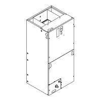
5. On both sides of the cabinet, remove the two screws that hold the
coil support brackets and retain for later use. Seal the holes to
prevent air leakage.
6. Rotate and lift the two coil support brackets to remove from front
slots in cabinet.
Figure 11. All models
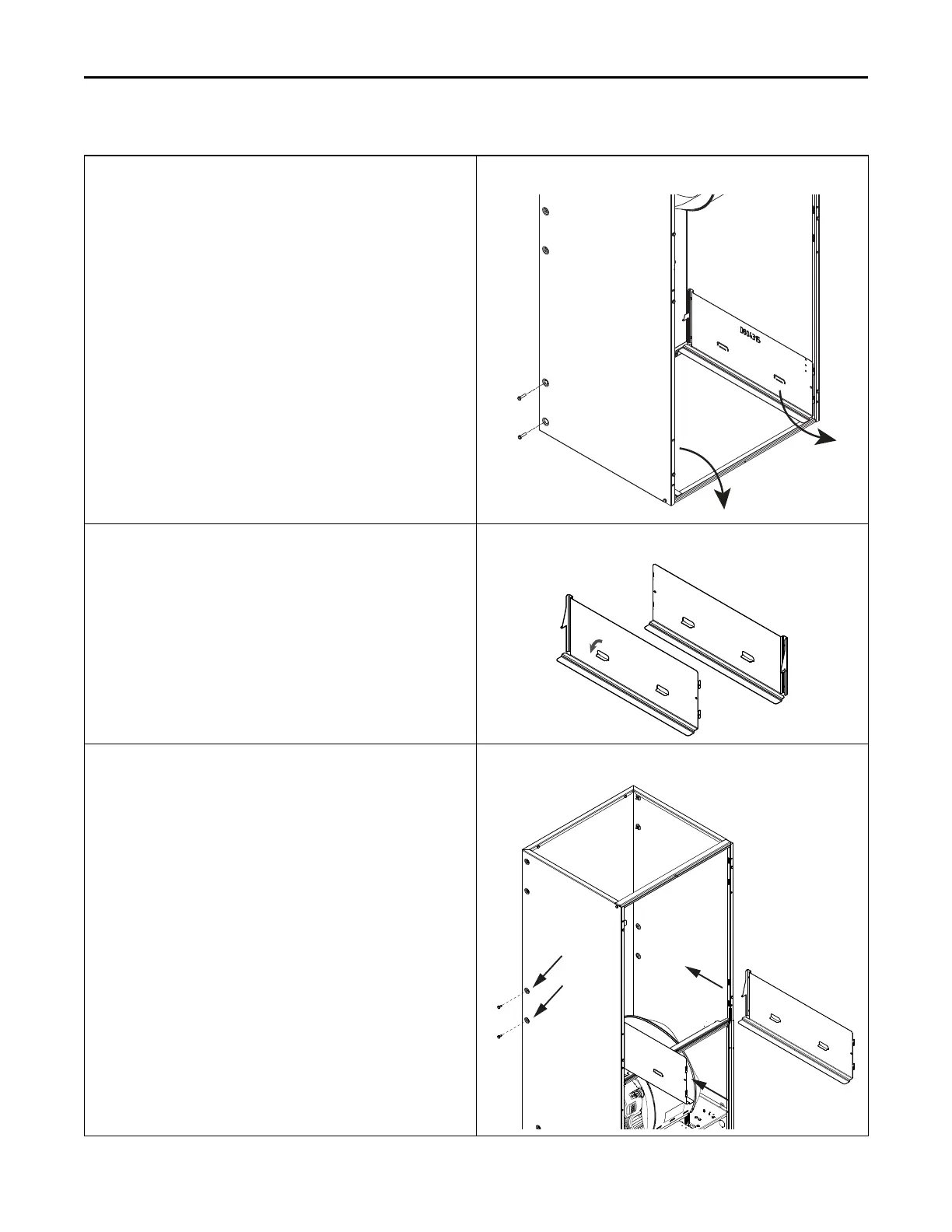
7. Bend the two tabs on each of the coil support brackets. Tabs
should be bent inward so they are parallel to the bottom flange.
Figure 12. All models
8. Rotate the unit into the downflow orientation.
9. Pre-drill four clearance holes in the cabinet at dimples located
below the location the screws were removed for the coil support
brackets. There are two holes per side. See location of holes.
10. Replace the center horizontal bracket removed in Step 3. Use the
screws retained from Step 3 to attach.
11. Place coil support brackets into the lower set of slots and rotate
into place. Push downward to lock into place.
12. Secure each bracket with 2 screws that were previously removed.
Figure 13. All models
CCooiill CCoonnvveerrssiioonn IInnssttrruuccttiioonnss
 Loading...
