4 88-A4HP4001-1F-EN
D
W
H
Section 2. Unit Location Considerations
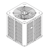
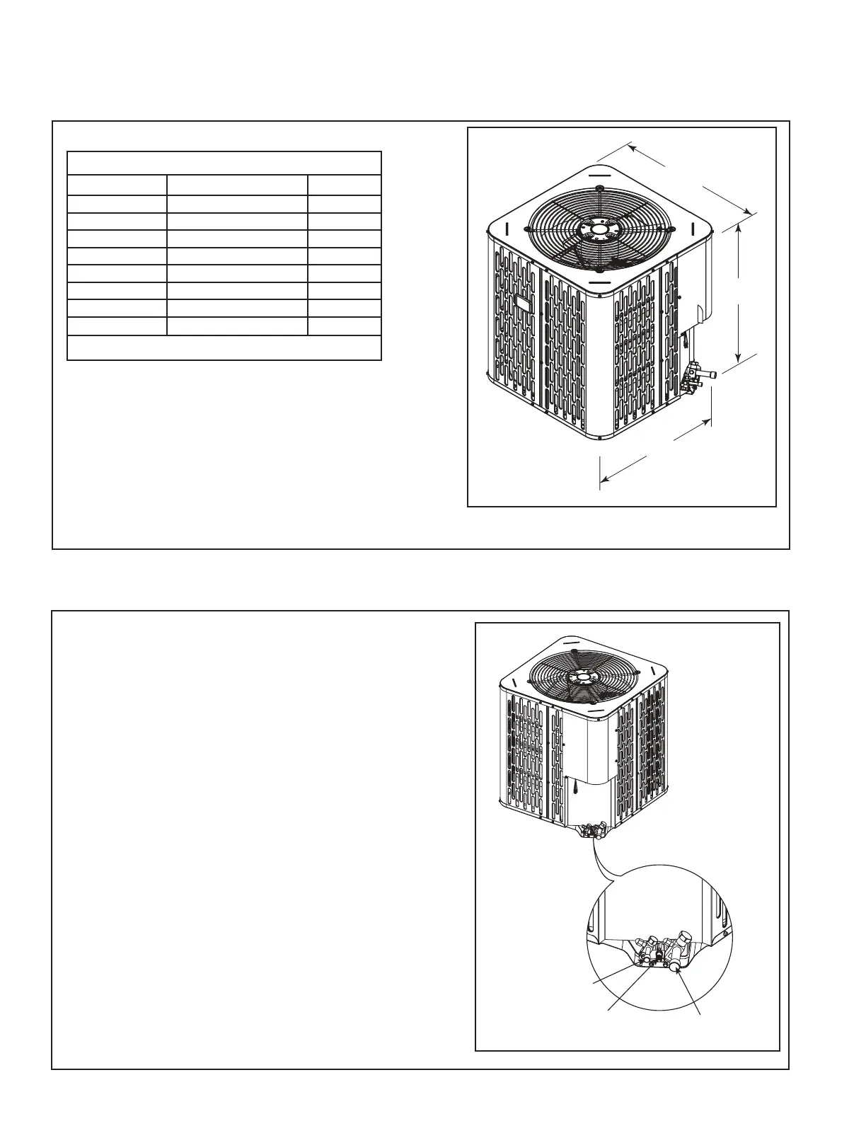
2.1 Unit Dimensions and Weight
Table 2.1
When mounting the outdoor unit on a roof, be
sure the roof will support the unit’s weight.
Properly selected isolation is recommended to
alleviate sound or vibration transmission to the
building structure.
Liquid Line Connection
Access valve for compressor
suction pressure measurement
Suction Line
Connection
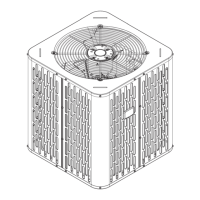
2.2 Service Valves Locations
1. The locations of the below listed valves in
the unit are shown in the figure.
a) Liquid line connection
b) Access valve for compressor suction
pressure measurement
c) Suction line connection
Unit Dimensions and Weight
Models H x D x W (in)
Weight* (lb)
A4HP4017D 28.6 X 25.6 X 25.6 143
A4HP4018D 32.6 X 29.8 X 29.8 162
A4HP4024D 32.6 X 29.8 X 29.8 162
A4HP4030D 28.6 X 29.8 X 29.8 159
A4HP4036D 36.6 X 34.3 X 34.3 199
A4HP4042D 44.6 X 34.3 X 34.3 227
A4HP4048D 44.6 X 34.3 X 34.3 250
A4HP4060D 44.6 X 34.3 X 34.3 250
* Weight values are estimated uncrated.
 Loading...