EasyManua.ls Logo

Trane A5AHC002A1B30A - User Manual

Trane A5AHC002A1B30A
36 pages
Print Icon
To Next Page IconTo Next Page
Loading...
SSAAFFEETTYY WWAARRNNIINNGG
Only qualified personnel should install and service the equipment. The installation, starting up, and servicing of heating, ventilating, and air-conditioning
equipment can be hazardous and requires specific knowledge and training. Improperly installed, adjusted or altered equipment by an unqualified person
could result in death or serious injury. When working on the equipment, observe all precautions in the literature and on the tags, stickers, and labels that
are attached to the equipment.
March 2024
1188--GGFF8811DD11--11AA--EENN
Convertible Air Handlers
2 5 Ton
A5AHC002A1B30A
A5AHC003A1B30A
A5AHC004A1D30A
A5AHC005A1D30A
A5AHC006A1D30A
A5AHC007A1D30A
The A5AHC series air handler is designed for installation
in a closet, utility room, alcove, basement, crawlspace or
attic. These versatile units are applicable to air
conditioning and heat pump applications. Several
models are available to meet the specific requirements of
the outdoor equipment. Field installed electric resistance
heaters are available.
Installation, Operation, and Maintenance
Question and Answer IconNeed help?

Do you have a question about the Trane A5AHC002A1B30A and is the answer not in the manual?

Overview

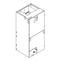
This document describes the installation, operation, and maintenance of Convertible Air Handlers, specifically the A5AHC series, designed for 2-5 ton applications. These versatile units are suitable for air conditioning and heat pump systems and can be installed in various indoor locations such as closets, utility rooms, alcoves, basements, crawlspaces, or attics. Field-installed electric resistance heaters are also available as an option.

Function Description

The A5AHC series air handler's primary function is to circulate conditioned air throughout a residential space as part of a heating, ventilating, and air-conditioning (HVAC) system. It works in conjunction with an outdoor unit (condenser for AC, heat pump for heating/cooling) to provide either cooling or heating. The unit is designed for multi-position installation (upflow, downflow, horizontal left, and horizontal right) to accommodate diverse building layouts. A key safety feature is the integrated refrigerant leak detection system, which automatically mitigates risks in case of a leak by turning on the blower, opening zoning dampers, turning off the outdoor compressor, and de-energizing potential ignition sources.

Important Technical Specifications

  • Models Covered: A5AHC002A1B30A, A5AHC003A1B30A, A5AHC004A1D30A, A5AHC005A1D30A, A5AHC006A1D30A, A5AHC007A1D30A.
  • Capacity: 2-5 Ton.
  • Refrigerant: Designed for use with R-454B.
  • Coil: All-aluminum coil, factory pressurized with 8-12 psi dry air and checked for leaks.
  • Drain Pans: Sturdy polycarbonate, factory installed for upflow applications.
  • Blower: Multi-speed direct drive blower.
  • Thermal Expansion Valve (TXV): Factory installed R-454B TXV.
  • Electrical Operation: 208/230 VAC operation.
  • Cabinet: Painted finish on galvanized steel exterior with fully insulated cabinet (R4.2 value).
  • Return Air: Bottom return.
  • Building Codes: Meets minimum leakage requirements for Florida and California Building Codes.
  • Minimum Conditioned Space: Varies by refrigerant charge and altitude, detailed in Table 3.
  • Clearances: Minimum service clearances are 2" for sides, 21" for front, 0" for back, and 1" for inlet duct.
  • Ductwork: Must be installed in accordance with NFPA No. 90A and 90B.
  • Condensate Drains: Primary and auxiliary drains with 3/4" NPT connections. Requires a trap outside the unit and proper downward pitch (1/4" per foot).
  • Refrigerant Piping: Must be protected from physical damage and comply with national and local codes. Field joints must be accessible for inspection.
  • Air Filter: Must be installed before air enters the evaporator coil and meet UL 900 test requirements.

Usage Features

  • Multi-Position Installation: Can be configured for upflow, downflow, horizontal left, and horizontal right applications. Specific coil, drain pan, and sensor repositioning may be required for horizontal right and downflow.
  • Airflow Adjustment: Factory configured for sufficient airflow. Adjustments for cooling, heat pump, and electric heater airflow are made by connecting green and pink wires to specific speed taps on the motor. The black wire always remains on Tap 1.
  • Two-Stage Airflow (Optional): Supports two-stage operation with Y1 and Y2 wiring for compatible thermostats. The blower motor is programmed to run low-stage when Y2 is not energized.
  • Refrigerant Leak Detection System: Automatically detects leaks, turns on the blower, opens zoning dampers, turns off the outdoor compressor, and de-energizes potential ignition sources. An audible alarm can be configured.
  • Thermostat Compatibility: Compatible with single or two-stage HP or AC heating/cooling thermostats with electric heat.
  • Defrost Support: Supplemental heat during defrost can be provided by connecting the X2 (black) wire from the outdoor unit to W1 or W2 at the indoor unit to prevent cold air discharge.

Maintenance Features

  • Air Filter: Inspect, clean, or replace monthly. Access panels must be properly secured after maintenance.
  • Periodic Maintenance: Annual maintenance by trained professional service personnel is recommended, including testing and inspection of electrical and refrigerant components, and cleaning the heat transfer surface.
  • Blower Motor: Permanently lubricated for normal operating conditions.
  • Refrigerant System: Requires proper handling of flammable refrigerants (R-454B) by trained service professionals. Procedures for leak detection, recovery, evacuation, and charging must be followed carefully, including pressure testing with nitrogen and vacuum testing to 350 microns.
  • Electrical Components: Repairs and maintenance to electrical components must adhere to manufacturer guidelines and safety checks, including ensuring capacitors are discharged, no live components are exposed, and earth bonding continuity.
  • Unit Conversion: Detailed instructions are provided for repositioning the refrigerant sensor, coil, and drain pan for different installation orientations (horizontal left, downflow, horizontal right).
  • Checkout Procedures: A comprehensive checklist is provided to ensure proper installation and function, covering wiring, voltage, refrigerant lines, leak checks, sensor relocation, ductwork, drain lines, registers, fan operation, and overall system safety.

Trane A5AHC002A1B30A Specifications

General IconGeneral
BrandTrane
ModelA5AHC002A1B30A
CategoryAir Handlers
LanguageEnglish

Related product manuals