14
18-GF81D1-1A-EN
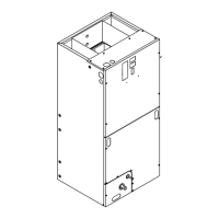
NNoottee:: Remove nitrogen pressure and repair any
leaks before continuing.
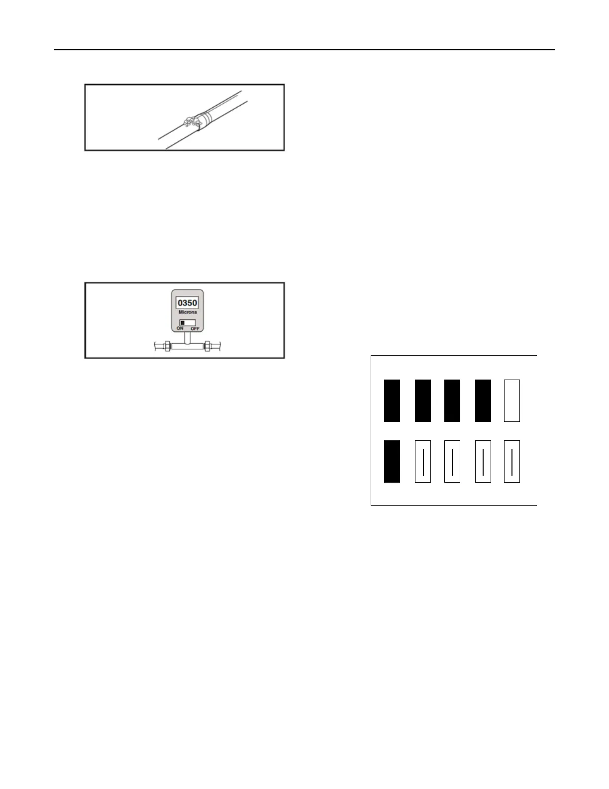
VVaaccuuuumm tteesstt::
IImmppoorrttaanntt:: Do not open the service valves until the
refrigerant lines and indoor coil leak
check and evacuation are complete.
• Evacuate until the micron gauge reads no
higher than 350 microns, then close off the
valve to the vacuum pump.
• Observe the micron gauge. Evacuation is
complete if the micron gauge does not rise
above 500 microns in one (1) minute and 1500
microns in ten (10) minutes.
• Once evacuation is complete, blank off the
vacuum pump and micron gauge, and close the
valve on the manifold gauge set.
All procedures for charging the system with
refrigerant shall be according to the instructions
provided by the manufacturer of the outdoor unit.
IImmppoorrttaanntt:: Under no circumstances shall potential
sources of ignition be used in the
searching for or detection of refrigerant
leaks.
After charging the system, all indoor field-made
joints of the field piping shall be checked for
refrigerant leaks using an electronic leak detector
calibrated for R-454B having a sensitivity of 5 grams
per year or better.
6. MMeetteerriinngg DDeevviiccee
All units are shipped and installed with an
internally-checked, non-bleed TXV designed for air
conditioning or heat pump operation. Some
outdoor models may require a start assist kit. See
outdoor unit for more information.
7. BBlloowweerr
This unit is supplied with a multi-speed motor with
a direct drive blower wheel which can obtain
various air flows. The unit is shipped with factory
set cooling and heating air flows. Performance
tables are available for additional airflow settings.
Disconnect all power to the unit before making any
adjustments to the airflow settings. Be sure to
check the air flow and the temperature drop across
the evaporator coil to ensure sufficient air flow.
NNoottee:: For optimal performance, seal the seams of
the front panels using an appropriate tape to
reduce air leakage.
8. AAiirrffllooww AAddjjuussttmmeenntt
Indoor airflow changes are made by connecting the
green wire and pink wire to the appropriate speed
taps on the motor as follows:
a. The black wire must always remain on Tap 1.
b. Cooling and Heat Pump Airflow Selection -
Place green wire on tap 2, 3, 4, or 5.
c. Electric Heater Minimum Airflow Selection –
Place the pink wire on any tap such that either
the green or pink wire meets the minimum
speed tap requirement shown on name plate.
d. Two-Stage Airflow Configuration (optional) -
Separately wire Y1 and Y2 at the field wiring
connections. No further adjustment necessary.
For cooling and heat pump airflow settings, refer to
the airflow tables in the Performance and Electrical
Data section of this manual.
To configure two-stage indoor airflow operation,
separately wire the Y1 (yellow) and Y2 (yellow/red)
wires in the low-voltage pigtail field connections to
a compatible two-stage thermostat. Refer to the
Field Wiring Diagrams section of this manual.
NNoottee:: The blower motor is programmed to run the
low-stage of the two-stage configuration
when Y2 is not energized (no additional tap
selection required).
If equipping an optional electric heater, the airflow
must be configured at or above the airflow
selection shown on the name plate or in the
Minimum Airflow CFM section of this manual.
IInnssttaallllaattiioonn IInnssttrruuccttiioonnss