88-A5HP4001-1A-EN 11
With Furnace
1. Units with pigtails require wirenuts for connections.
Cap all unused wires.
2. For 24V control, connect factory supplied harness to
circuit board at evaporator.
Complete all other wiring connections at the furnace
3. For 2 stage systems, connect W2 to W2 and Y2 to Y2.
Thermostat
Evaporator Coil MCB
Outdoor
Unit
Furnace
R
G
B
R
G
B
B
R
G
B/C
Y
W1
W2
R
24 VAC HOT
FAN
24 VAC
Common
COOL
HEATING
BK BK BKi
O O
Y
l
Y
l
Y
O
Y2
X2
R
G
B
W1
W2
BK
O
Y
l
Y/Y1
Y2
3)
3)
3)
3)
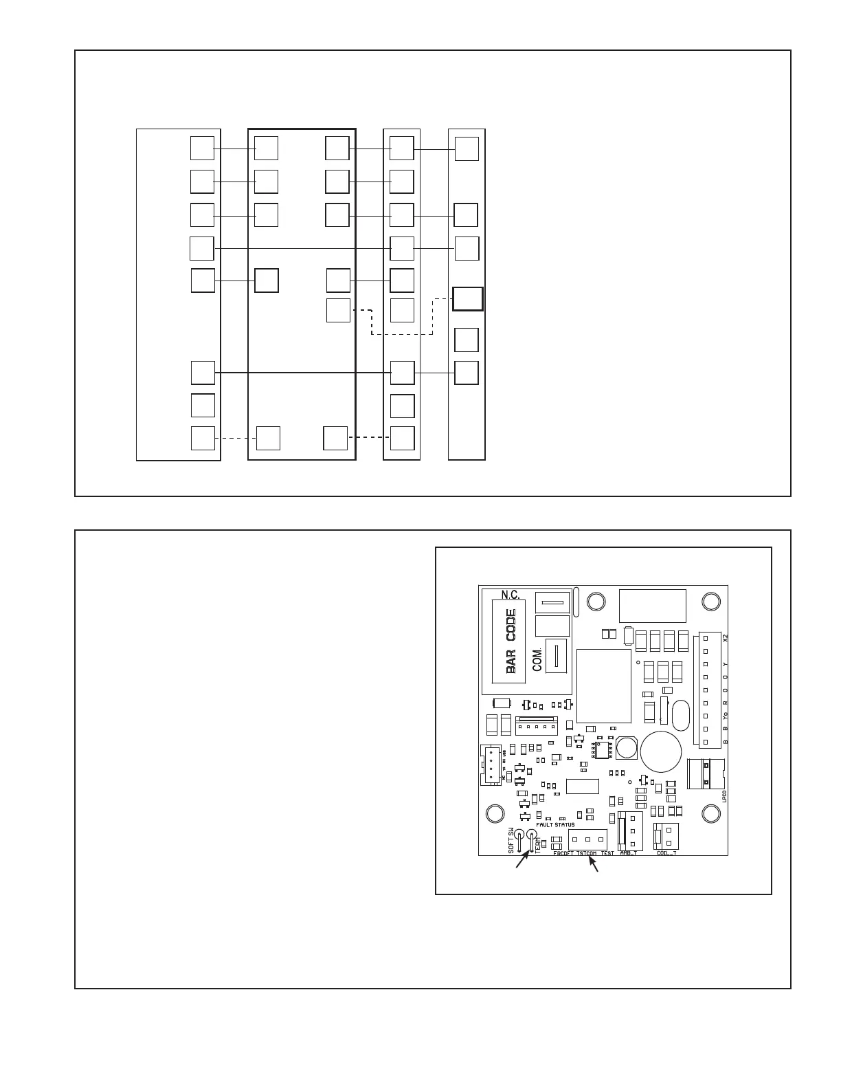
Defrost controls have a selectable termination tem-
perature. As shipped, defrost will terminate at 47°F.
For a higher termination temperature, cut Jumper
J2 to achieve 70°F. Refer to the Defrost Control
section in this document for more information.
Pin Identification on J5 (See Illustration)
1. TEST_COMMON (Shorting to FRC_DFT
causes the control to initiate Forced Defrost.
Leaving this pin open results in the normal
mode of operation.)
2. FRC_DFT = Forced Defrost (Short TEST_
COMMON to this pin for two (2) seconds to
initiate a forced defrost. Remove the short
after defrost initiates.)
Defrost Control Checkout
Normal operation requires:
• Status LED on board flashing 1 time/second
in standby or 2 times/second with a call for
heating or cooling.
• 24V AC between R & B
• 24V AC between Y, Y0 & B with unit operating
• Defrost initiation when FRC_DFT pin is shorted to TEST_COMMON pin.
If a defrost control problem is suspected, refer to the service information in control box.
Defrost Board Detail
JPR2
JPR1
K1
J4
K2
K3
J9
J8
J3
J5
J2
J1
Jumper J2
J5 Test Pins
11.3 Defrost Control - All Models except 036