98 CLCH-SVX07C-EN
Installation - Electrical
Note: Properly seal all penetrations in unit casing. Failure to seal penetrations from inner panel
to outer panel could result in unconditioned air entering the unit.
All units with starters or variable-frequency drives (VFDs) that have direct-digital controllers (DDCs)
are provided with line voltage to 24 Vac power transformers (see Figure 86). All units with factory-
mounted controllers, and no starters or VFDs, are provided with 120 Vac to 24 Vac control
transformers (see Figure 87). Figure 88 shows a typical VFD power box.
Note: The valve jack is typically located at the air-leaving side of the coil connection inside the
casing panel.
To provide field-wiring to units with DDC controls:
• If VFD or starter is not factory-mounted, provide 120 Vac power to a transformer in the controller
enclosure. A separate circuit is recommended (see Figure 87).
• Install outside-air sensor and space sensor, if ordered.
• For valve junction box mounting and wiring detail, see Figure 89.
Figure 86. Transformer plate
Figure 87. 120 to 24 Vac Control
Transformer
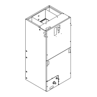
Figure 88. Variable-frequency drive
(VFD)
 Loading...