CLCH-SVX07C-EN 99
Installation - Electrical
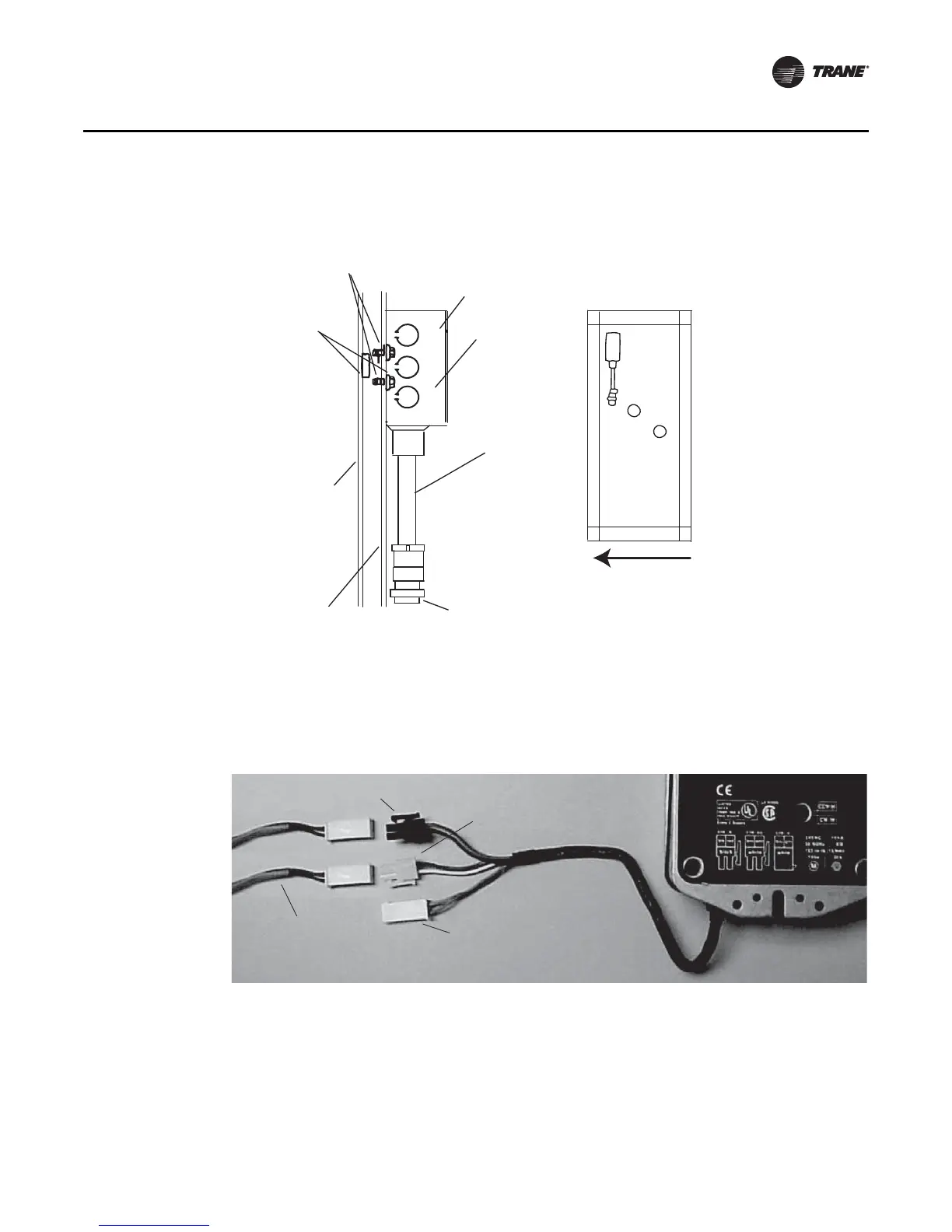
Quick Connects
The actuators, factory-mounted or field-supplied, are separately wired and controlled by a direct-
digital controller or other building logic. Figure 90 illustrates the typical quick connect scheme.
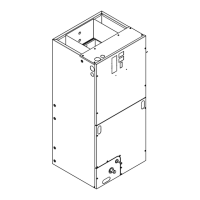
Figure 89. Junction box for valve wiring
#10 self-drilling
screws (2)
2 x 4 junction box
Cover
Conduit
assembly
Valve
connection
End panel
Double-
wall panel
Bushing
(2 required
for units with
double-wall)
Airflow
Figure 90. Typical quick connects with wiring identification
Actuator
Power 24 Vac
Control signal
(2-10 Vdc)
Feedback signal
(not factory-wired,
used for factory test)
Wiring harness
 Loading...