19
Plenum Installation
1. Assemble the plenum using the plenum’s
Installer Guide.
Airflow
7.5 Downflow Installation
• Downflow installation must comply with national,
state, and local codes.
• The air handlers are rated for zero clearance from
combustible materials.
STEP 1 - Prepare the location site as appropriate for
your application and per national, state, and local code
requirements.
STEP 2 - Set the unit in position.
Representative Illustration
Typical Downflow Installation
On units with sheet metal returns: Return plenum
must be flanged. Sheet metal drill point screws
must be 1/2” in length or shorter.
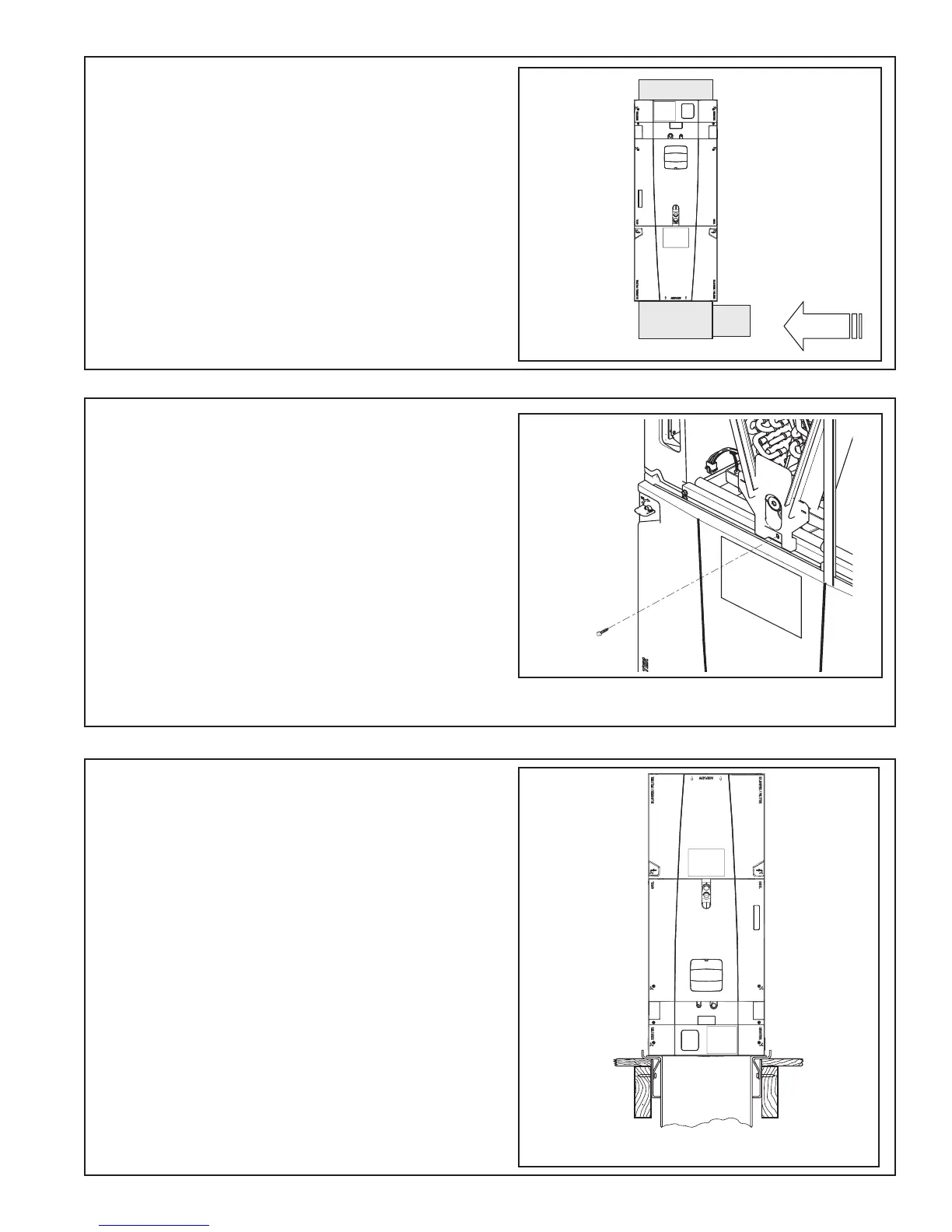
7.4 Secure Coil (Downflow Applications)
STEP 1 - Remove Coil Panel.
STEP 2 - Remove screw from documentation packet.
STEP 3 - While the air handler is in the upflow posi-
tion, use the supplied screw to secure the coil seal
plate to cross member as shown.
Important: The Coil Seal Plate and screw secure the
coil in the center of the air handler. Failure to follow
these steps can prevent the Coil Panel from being
easily replaced on the unit.
Important: For the 5 ton air handler model
*AM4A0C60S51SA, tap 5 should not be used in the
downflow or horizontal orientations. Using Tap 5
could result in water blowing off the coil.
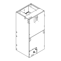
Typical Plenum Installation
Important: Ensure EEV sensor and motor wiring
are taught and wire-tied to the distributor tube to
prevent damage during electric heat operation.
 Loading...