Damper Troubleshooting
The following is a possible cause and correction list for common concerns with the dampers.
Symptom Possible Cause Corrective Action
Damper does not fully
open and/or close
Frame is 'racked' causing blades to bind
on jamb seals
Adjust frame such that it is square and plumb
Actuator linkage loose Close damper, disconnect power, adjust and tighten
linkage
Defective motor Replace
Screws in damper linkage Damper installed too far into wall. Move out to line as
designated on damper label
Contaminants on damper Clean with a non-oil based solvent (see Damper
Maintenance)
RRL or TOR sensor
tripped
Heat Push reset button located on backside of RRL or TOR
Damper does not oper-
ate
No power supplied to the actuator Add power supply
Damper Maintenance
Dampers do not typically require maintenance as long as they are kept dry and clean. If cleaning is necessary, use mild
detergents or solvents. If lubrication is desired for components such as axle bearings, jackshaft bearings and jamb
seals, do not use oil-based lubricants or any other lubricants that attract contaminants such as dust.
Dampers and their actuator(s) must be maintained, cycled, and tested a minimum in accordance with:
• ThelatesteditionsofNFPA80,90A,92A,92B,101,105,UL864,AMCA503-03andlocalcodes.
• Actuatormanufacturerrecommendations.
Copyright © 2010 Greenheck Fan Corporation
IOM461336FSDRev.15October2010
8
Duct
Sleeve
6 in.
Std. Clip
Length
C
L
Duct
60 in. Duct
4 Req’d.
48 in. Duct
3 Req’d.
36 in. Duct
3 Req’d.
24 in. Duct
2 Req’d.
18 in. Duct &
Smaller
1 Req’d.
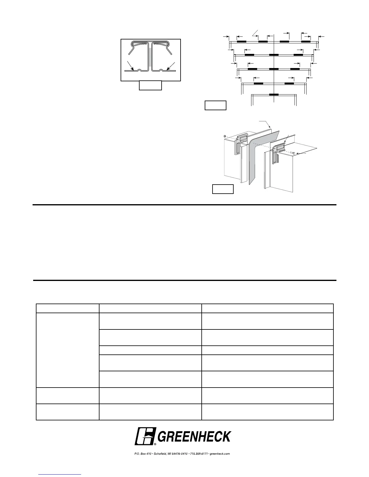
Clip Spacing
Typical TDC/TDF joint
6 in. 6 in.
9 in.
7 in.7 in.
5 in. 5 in.
5 in.5 in.
Fig. 16
6 in.
Std. Clip
Length
C
L
Duct
60 in. Duct
4 Req’d.
48 in. Duct
3 Req’d.
36 in. Duct
3 Req’d.
24 in. Duct
2 Req’d.
18 in. Duct &
Smaller
1 Req’d.
Clip Spacing
6 in. 6 in.
9 in.
7 in.7 in.
5 in. 5 in.
5 in.5 in.
Fig. 17
Duct End
Flange
Corner Piece
3/8 in. bolt
(optional)
Fig. 18
Proprietary Flange System Breakaway Connections
(TDC by Lockformer, TDF by Engle)
TDC and TDF systems are
approved as breakaway
connections when installed as
described in the TDC or TDF
addendum to the SMACNA Duct
Construction. Standard 6 in.
(152mm) metal clip may be used
with spacing as shown in diagram
(see Fig. 15 & 16). 3/8 in. (9.5mm)
metal bolts and nuts may be used to fasten together
corner pieces. (see Fig. 17)
 Loading...