CLCH-SVX07C-EN 45
Installation - Mechanical
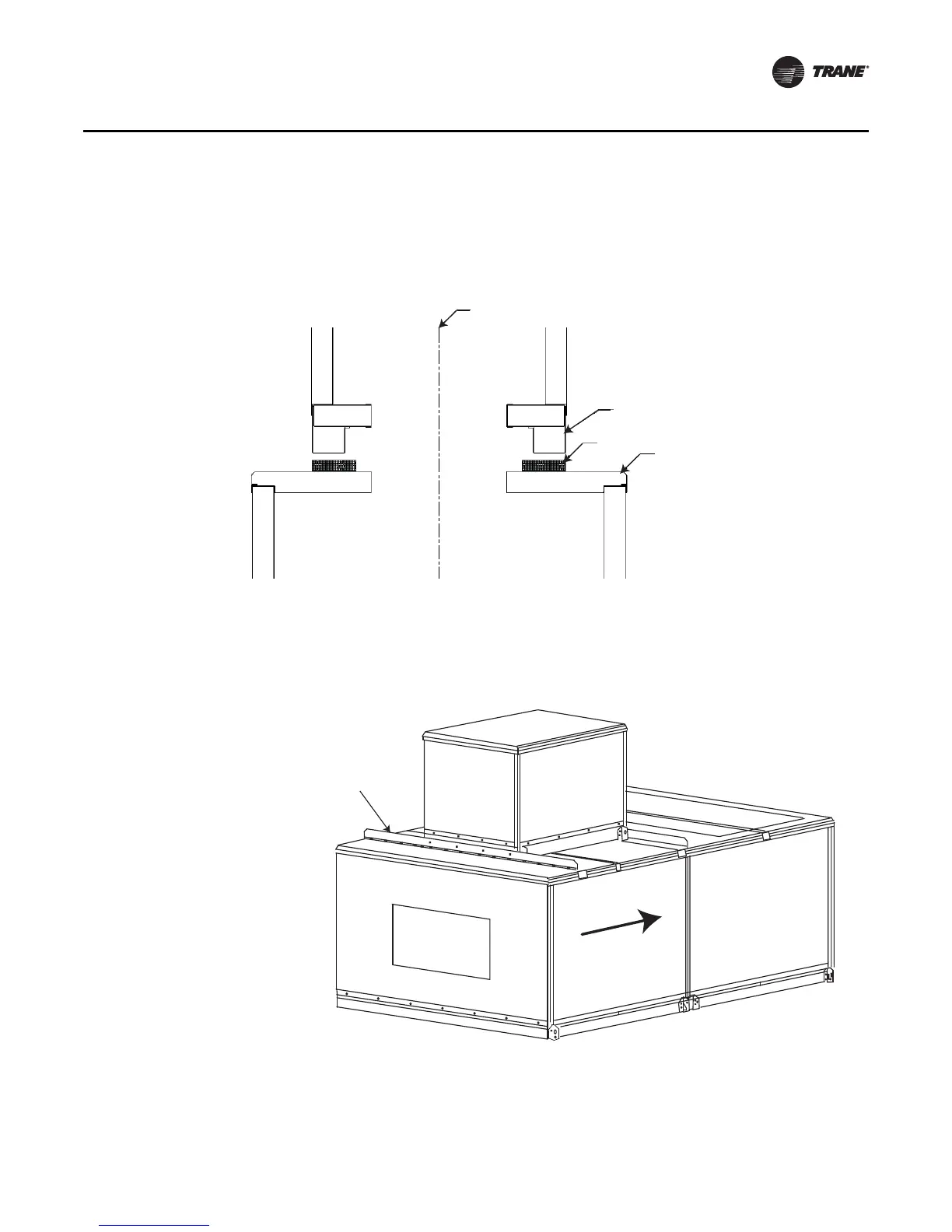
4. Lift the secondary unit, following instructions in “General Lifting Considerations” on page 25
(see Figure 6), and place on the black unit support brackets (see Figure 33). The secondary unit
must be centered on the primary unit between the black unit support brackets.
5. Install screws as shown in Figure 34 inserting the appropriate screws using a powered impact
gun and taking care not to strip the screws.
6. Remove the secondary unit lifting lugs one at a time and reinstall screws after sections are set
in final position.
Figure 33. Place secondary unit on black unit support brackets.
Figure 34. Install screws using powered impact gun.
Center of units
Secondary Unit
Gasket
Primary Unit
Airflow
X25240049010
Screw: 0.313-18 x 0.875 in.
Sheet metal hex head
 Loading...