6
18-HH36D1-1A-EN
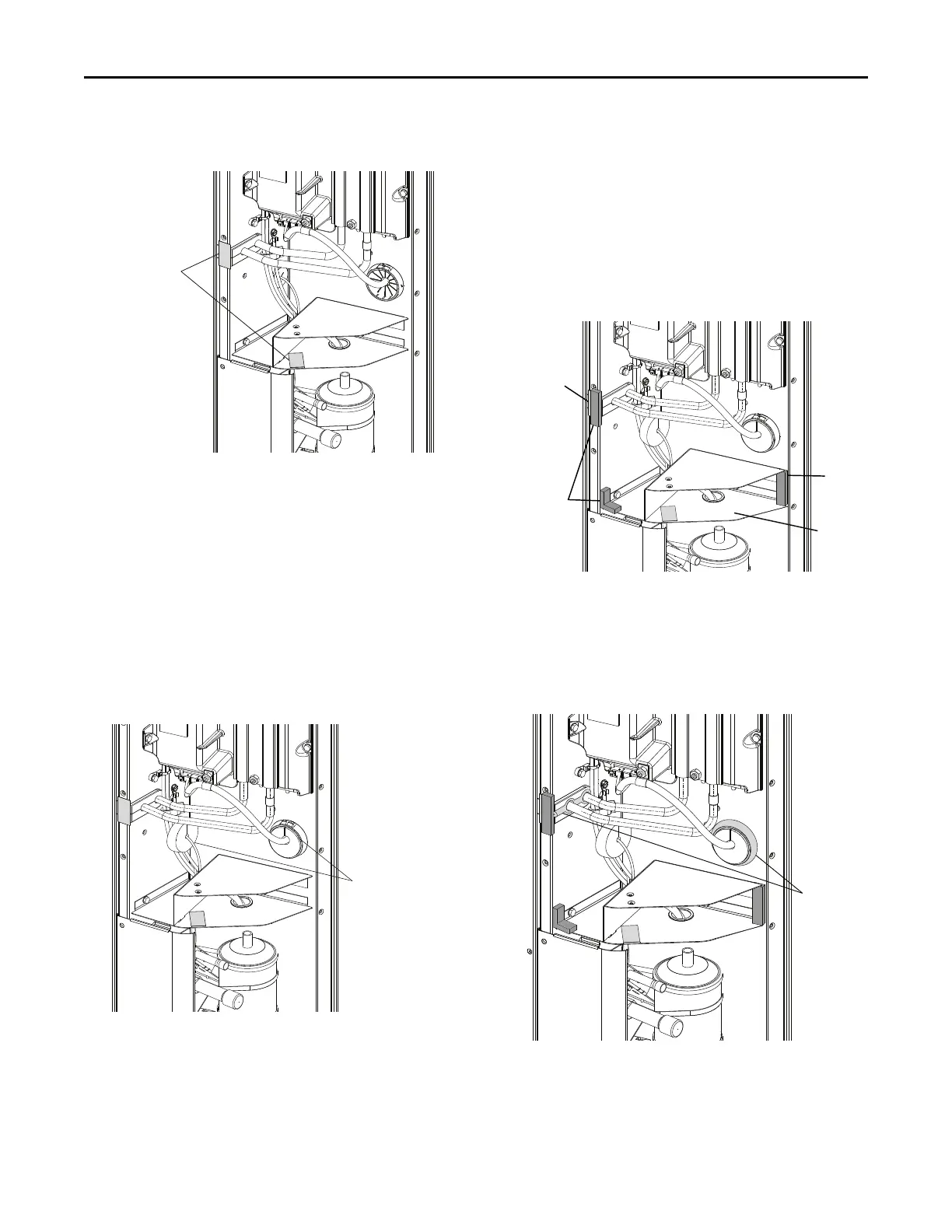
Figure 4. Duct Tape Installation
2. Install Foam in the Control Box.
a. Remove the adhesive backing from two (2)
grommets.
b. Attach one (1) grommet onto the compressor
harness. Make sure the split side of the
grommet is as closed as possible. See
Figure 5, p. 6.
c. Attach the other grommet onto the harness
grommet. Make sure the split side of the
grommet is as closed as possible. See
Figure 5, p. 6.
Figure 5. Grommets Installation
d. Make sure the grommets are sealed properly
around the harnesses.
e. Locate three (3) short foam pieces from the kit
contents and remove the adhesive backing from
all the short foam pieces.
f. Attach two (2) short foam pieces each on the left
side and right side of the bottom plate to seal
the gaps. See Figure 6, p. 6.
g. Attach the other short foam piece onto the duct
tape and the grommet on the copper tube. Make
sure the right side face of the short foam piece
is flush against the front face of the grommet.
See Figure 6, p. 6.
Figure 6. Install Short Foams
Short
Foam
Short
Foam
Bottom
Plate
Duct
Tape
3. Apply Silicone.
a. Use silicone to seal gaps around the copper
tube and the plastic compressor grommets. See
Figure 7, p. 6.
Figure 7. Apply Silicone
IInnssttaallllaattiioonn IInnssttrruuccttiioonnss