18-HH36D1-1A-EN
7
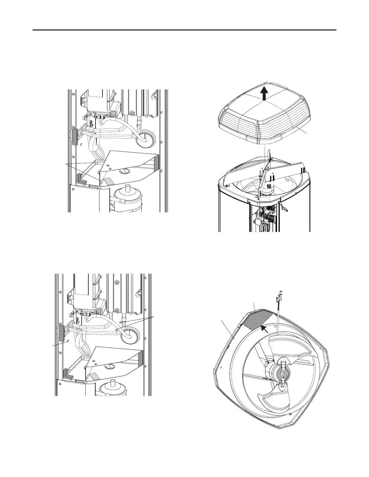
b. Use silicone to seal the gaps between the two
sheet metal parts and between the bottom plate
and rear wall. See Figure 8, p. 7.
Figure 8. Silicone on Sheet Metal Parts
c. Seal the unused screw holes with silicone in the
control box. See Figure 9, p. 7.
NNoottee:: The number of unused holes may vary
depends on the type of variable speed
models used.
Figure 9. Silicone on Empty Screw Holes
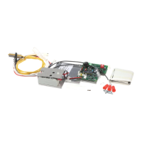
4. Install Foam to the Unit Top.
a. Remove the unit top. See Figure 10, p. 7.
Figure 10. Unit Top Removal
b. Remove the fan and fan shroud to gain access
to the bottom of the shroud. Take the top foam
piece, remove the adhesive backing and attach
it onto the top of the existing foam piece on the
bottom of the shroud. See Figure 11, p. 7.
Figure 11. Install Foam - Fan Shroud
IInnssttaallllaattiioonn IInnssttrruuccttiioonnss