ACC-SVN28A-EN 4
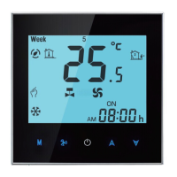
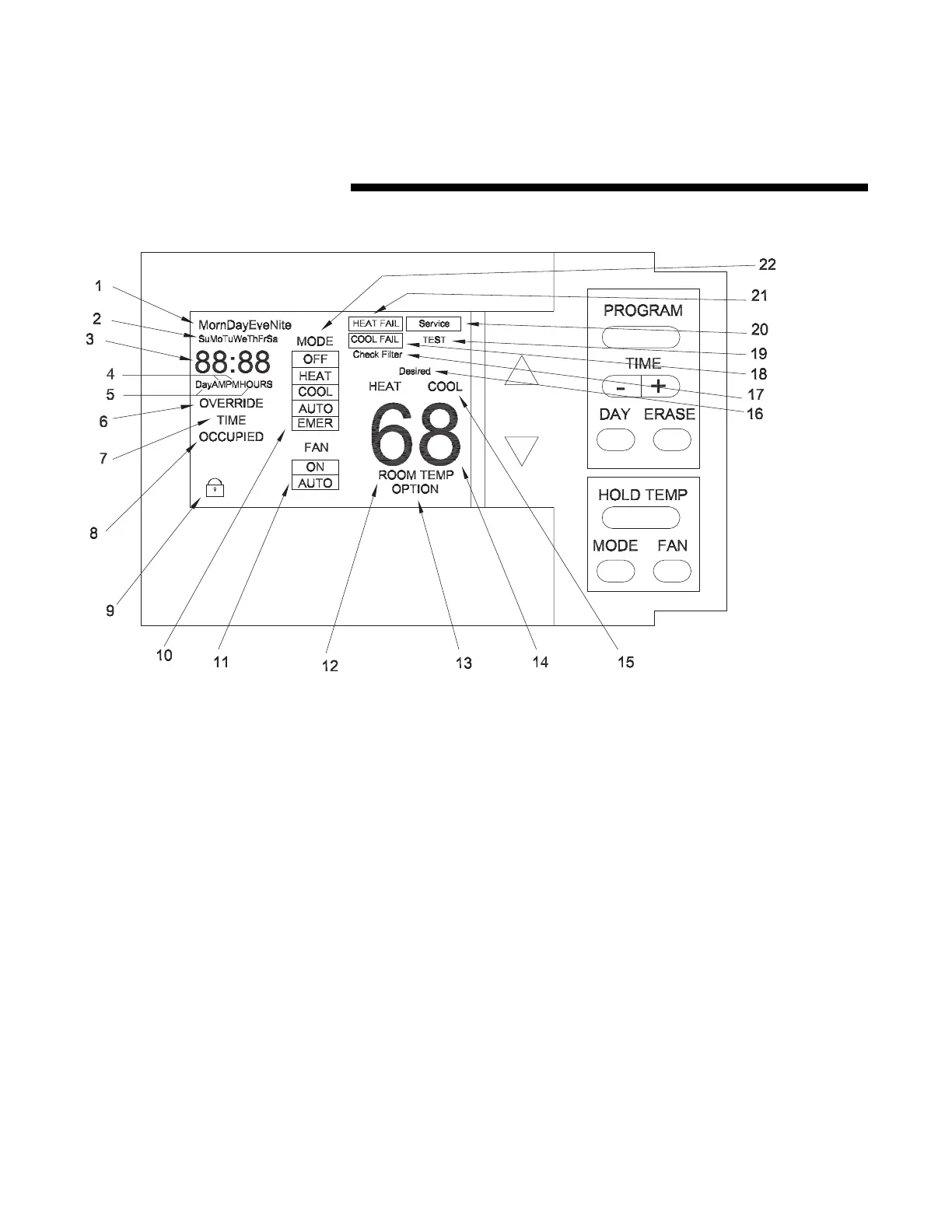
1 - The four periods of the day used
during programming.
2 - The seven days of the week used
during programming and in the
Normal Run State to indicate the
current day.
3 - Four digits used to display the
time of day in the Normal Run State.
Also used in the Programming
Menu, Temporary Override Menu,
and the Options Menu. The Colon (:)
blinks in the Normal Run State to
indicate communication to the UCP
is functioning.
4 - AM and PM used to display the
time of day (Morning/Evening) in the
Normal Run State when using the 12
hour time option.
5 - Days and Hours are used in the
Temporary Override Menu to
program the override time period.
6 - Displayed and Blinks during
Temporary Override Operaton.
7 - Displayed in the Temporary
Override Programming Menu.
8 - Programmable in the
Programming Menu and is displayed
in the Normal Run State to indicate
the current Zone Status.
9 - When displayed, indicates the
keypad is locked out. To lock or
unlock the keypad when this icon is
shown, press and hold the positive
(+) and negative (-) side of the TIME
key simutaneously.
10 - Emergency Heat selection
available when used with a
heatpump application and
programmed in the Options Menu.
11 - Displays the FAN operation
Mode.
12 - Displayed in the Normal Run
State when the Zone Temperature is
programmed to be displayed in the
Options Menu.
13 - Displayed only in the Options
Menu.
14 - Two digits used to display the
Zone Temperature when
programmed in the Options Menu.
15 - Indicates unit operating status in
the Normal Run State and is used in
the Programming Menu and
Temporary Override Menu to set the
desired operating setpoints.
16 - Displayed in the Programming
Menu and Temporary Override Menu
to indicate the desired operating
setpoints.
17 - Displayed and Blinks when the
programmed Check Filter time has
elapsed.
18 - Displayed and Blinks when a
Cooling Failure has occured.
19 - Displayed during the unit self-
test mode.
20 - Displayed and Blinks during
Service Status and if Fan Failure
occurs.
21 - Displayed and Blinks when a
Heating Failure has occured.
22 - Displays the System operation
Mode.
General Information