11
11UNT-PRC002-GB
Sound power levels
Discharge
Measurement conditions:
Measurements taken in a room adjacent to the room containing the FWD, at the outlet of the rectangular duct (1.5 m
long) fixed to its discharge opening.
Fan Power level in dB(A), per Hz frequency band Overall power
Unit speed 125 250 500 1000 2000 4000 8000 dB(A)
1 55 50 42 37 37 31 30 46
FWD 08 2 57 54 47 40 30 38 40 50
3 58 57 50 42 32 40 43 53
1 57 51 45 42 34 33 28 48
FWD 10 2 58 54 48 45 38 39 35 51
3 60 58 50 48 40 42 39 54
1 57 51 45 42 34 33 28 48
FWD 12 2 58 54 48 45 38 39 35 51
3 60 58 50 48 40 42 39 54
1 56 62 50 48 39 38 36 56
FWD 14 2 61 66 55 53 47 46 45 60
3 63 69 58 56 50 50 49 63
1 57 63 51 49 40 39 37 57
FWD 20 2 61 66 55 53 47 46 45 60
3 63 69 58 56 50 50 49 63
Intake
Measurement conditions:
Measurements taken at the horizontal air intake.
Fan Power level in dB(A), per Hz frequency band Overall power
Unit speed 125 250 500 1000 2000 4000 8000 dB(A)
1 56 55 55 53 46 45 42 57
FWD 08 2 63 62 60 60 53 53 53 64
3 66 65 63 62 56 55 57 67
1 62 58 55 58 51 48 44 61
FWD 10 2 66 63 60 62 56 55 52 66
3 70 67 63 65 59 59 57 69
1 62 58 55 58 51 48 44 61
FWD 12 2 66 63 60 62 56 55 52 66
3 70 67 63 65 59 59 57 69
1 66 65 65 65 57 50 46 68
FWD 14 2 73 72 69 71 64 59 57 74
3 78 76 73 75 69 64 63 78
1 68 72 64 64 56 52 50 69
FWD 20 2 76 76 68 71 65 61 61 75
3 78 79 71 74 69 66 66 78
AH-SVX03C-GB
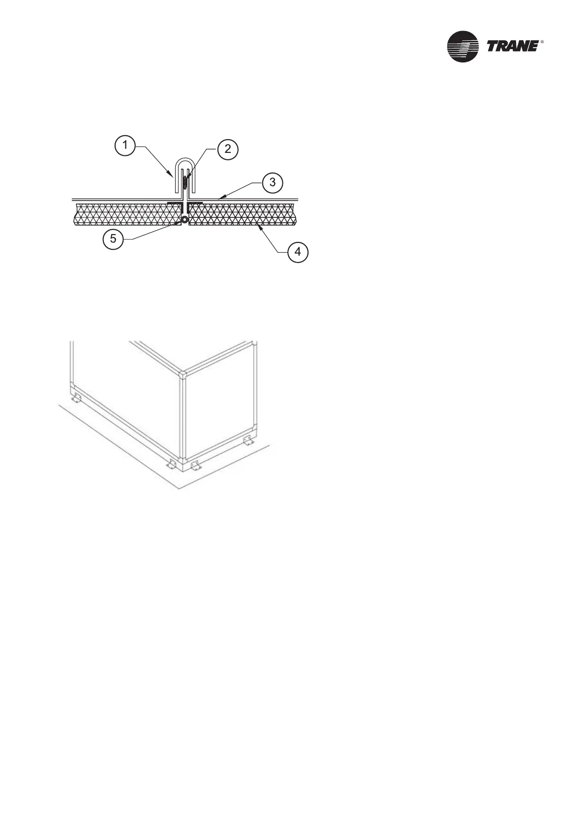
Figure 3 –
Gasket positioning
1 = Roof profile (supplied by Trane and to be installed on the jobsite)
2 = Silicone - not supplied by Trane
3 = Roof - factory-installed. The roof protrudes 20 mm on each side of the unit
4 = Panel
5 = Factory-installed gasket to be covered by a layer of Silicone (not supplied by Trane) for outdoor installation
Figure 4 –
Fixing of the unit
Remove the mounting vibrator blocks before starting the unit. They are just used to ensure safe transportation.
To minimize noise transmission, depending on the site location, additional insulation material such as cork slabbing,
Mafund slabbing or Sylomer strip insulation may be used as underlay. To obtain the maximum noise transmission
absorption, the selected materials must withstand the inherent load carrying characteristics. The list of application
requirements for these materials is provided by the products manufacturer. The load carrying capacities may be
indicated on the data sheets.
CAUTION! Failure to provide a level plinth or support will result in doors jamming and air leaks from the casing.
CAUTION! In the case that the unit is supplied with base frame, it shall be positioned on the supporting structure/
floor with a continuous and uniform contact between the base and the floor.
CAUTION! For outdoor installation to avoid water inside the unit, it is mandatory to cover the gasket positioned
between sections with a layer of silicone.
CAUTION! To avoid damage during transportation and handling, casing panels are supplied with a protective film
which needs to be removed on job site, as soon as the units are in place. Cut the protection film with a cutter around
the panels and remove it.
CAUTION! If the units have to be inspected by Consulting Engineers, contractors or any subsequent viewers at the
final stage of the installation, we strongly recommend protecting the units with plastic covers from the assembly up
to commissioning.
Installation