34
4 UNT-PRC002-GB
Technical Data
FWD 08 12 20 30 45
Power supply (V/Ph/Hz) 230/1/50
Capacities
Cooling capacity on water (1) (kW) 5,2 8,3 15 18,8 30,1
Heating capacity on water (2) (kW) 6,3 11,9 18,9 20,9 38,2
Fan motor (type) 2 x direct drive centrifugal
Fan power input (3) (kW) 0,23 0,46 0,65 1,04 1,51
Current amps (3) (A) 1,1 2,2 3,1 4,7 5,5
Start-up amps (A) 3,2 5,5 9,3 14,1 16,5
Air flow
minimum (m
3
/h) 490 980 1400 1800 2700
nominal (m
3
/h) 820 1650 2300 3000 4500
maximum (m
3
/h) 980 1970 2600 3600 5400
Main coil
Water entering/leaving connections (type) ISO R7 rotating female
(Dia) 3/4" 3/4" 1 1/2" 1 1/2" 1 1/2"
Electric heater (accessory for blower only)
Electric power supply (V/Ph/Hz) 230/1/50 230/1/50 or 400/3/50 400/3/50 400/3/50 400/3/50
Heating capacity (kW) 2/4 8 10 12 12
Hot water coil (accessory for blower only)
Heating capacity (4) (kW) 6,3 12 17,4 22,4 34,5
G2 filter (filter box accessory)
Quantity 2 2 2 2 2
Dimensions ( LxWxth) (mm) 386x221x8 486x271x8 586x321x8 586*421*8 586*621*8
G4 filter (filter box accessory)
Quantity - 2 2 2 2
Dimensions ( LxWxth) (mm) - 486x264x48 586x314x48 586*414*48 586*614*48
Condensate pump (accessory) (type) Centrifugal
Water flow - lift height (l/h - mm) 24 - 500
Not available for FWD30 and FWD45
Sound level (L/M/H speed)
Sound pressure level (5) (dB(A)) 36/40/43 38/41/44 46/50/53 47/52/57 47/52/58
Sound power level (5) (dB(A)) 46/50/53 48/51/54 56/60/63 57/62/67 57/62/68
Unit dimensions
Width x Depth (mm) 890 x 600 1090 x 710 1290 x 820 1290 x 970 1290 x 1090
Height (mm) 250 300 350 450 650
Shipped unit dimensions
Width x Depth (mm) 933 x 644 1133 x 754 1333 x 864 1333 x 1008 1333*1133
Height (mm) 260 310 360 460 660
Weight (kg) 32 46 61 76 118
Colour galvanised steel
Recommended fuse size
Unit alone (aM/gI) (A) 8/16 8/16 8/16 8/25 8/25
Unit with electric heater (gI) (A) 16 (2kW),25 (4kW) 40 (230V),3*16 (400V) 3*20 3*25 3*25
(1) Conditions: Water entering/leaving temperature: 7/12 °C, Air inlet temperature 27/19°C DB/WB - Nominal air flow
(2) Conditions: Water entering/leaving temperature: 50/45 °C, Air inlet temperature 20°C DB - Nominal air flow
(3) At high speed with nominal air flow.
(4) Water entering/leaving temperature 90/70 °C, air inlet temperature 20 °C DB, Nominal air flow.
(5) A rectangular glass wool duct 1m50 long is placed on the blower.The measurement is taken in the room containing the blower unit.
Heat exchanger operating limits:
FWD:
*water temperature: max 100° C
*absolute service pressure: min 1 bar/max 11 bars
Accessories - Hot water coil:
*water temperature: min. +2° C/max. 100° C
*absolute service pressure: min 1 bar/max 11 bars
AH-SVX03C-GB
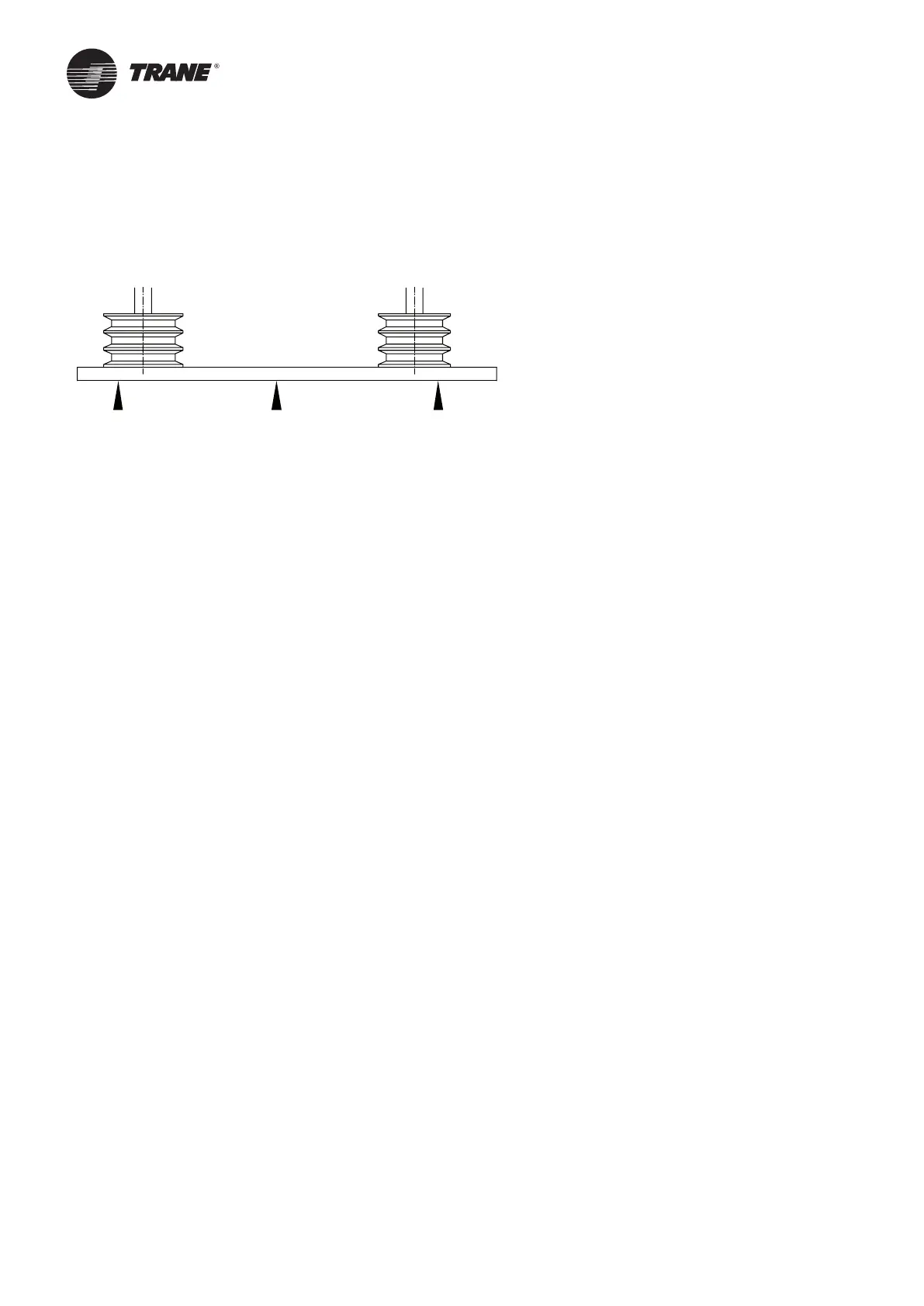
Pulley alignment
Check using a straight edge along both pulleys (See Figure 24). It is recommended to use a metal ruler instead of
a string.
Correct position is showed on Figure 24.
Figure 24 –
Pulley alignment
Pulley removal
Pulleys are generally mounted with a conic joint.
To remove pulleys, follow the manufacturer's directions.
Pulleys not provided with a conic joint are mounted by forcing them onto the shaft.
To remove them, heat the pulley hub and use a pulley extractor.
Belt replacement
To change the belt, the belt tensioning device is slackened off until the worn belt can be removed.
Before the replacement, clean the pulleys and check them for damage and wear.
Never use tools or force on the pulley edges as invisible damage can significantly reduce the life of these items.
If multi pulleys are in use all belts must be replaced simultaneously.
Check that the number of belts matches the number of pulley grooves.
During the tensioning of multiple belts in parallel, it is important that they are all slack on the same side of the drive
mechanism otherwise damage can result.
Finally, when the belts are tensioned, the drive must be turned for a few revolutions by hand and then the state of
tension, the shaft sand pulley layout are checked (see Drive belt tensioning section).
Coils
If a unit is not run for an extended period of time, it is recommended to completely drain off the coil. When refilling is
undertaken, check that the unit is effectively vented.
Periodic verification of coil cleanliness is required. Dirty coil shave increased air side pressure drops and reduced
heat transfer potential, disturbing the complete system balance.
Hot water, cold water, and steam coils
Coils do not require any special maintenance except regular cleaning.
Depending on the amount of operational usage and filter servicing, check the coil finned area for dust and deposits,
roughly every 3 months and clean as necessary.
Also check that the pipe work is watertight.
Cleaning
The cleaning is carried out with the coil in place using a powerful vacuum cleaner on the dust contaminated side.
If the coil is very dirty it will need to be removed and wet cleaned. Zinc plated steel heat exchangers maybe cleaned
with a steam jet or the fins washed through with a powerful water jet and finally blown out with pressurized air.
If required, soft cleaning brushes may be used ensuring that the heat exchanger fins are not damaged.
CAUTION! Coils with copper or aluminium fins are particularly vulnerable and must therefore only be cleaned with
a low pressure water jet. In case of specific clogging, call a cleaning specialist; Trane cannot be held responsible for
improper cleaning of the coils. Any damage to the fins by the use of undue force will result in premature failure of
the heater coil.
Any points corroded or rusted should be cleaned off and coated with a zinc-based protective paint.
Maintenance