19
11UNT-PRC002-GB
Sound power levels
Discharge
Measurement conditions:
Measurements taken in a room adjacent to the room containing the FWD, at the outlet of the rectangular duct (1.5 m
long) fixed to its discharge opening.
Fan Power level in dB(A), per Hz frequency band Overall power
Unit speed 125 250 500 1000 2000 4000 8000 dB(A)
1 55 50 42 37 37 31 30 46
FWD 08 2 57 54 47 40 30 38 40 50
3 58 57 50 42 32 40 43 53
1 57 51 45 42 34 33 28 48
FWD 10 2 58 54 48 45 38 39 35 51
3 60 58 50 48 40 42 39 54
1 57 51 45 42 34 33 28 48
FWD 12 2 58 54 48 45 38 39 35 51
3 60 58 50 48 40 42 39 54
1 56 62 50 48 39 38 36 56
FWD 14 2 61 66 55 53 47 46 45 60
3 63 69 58 56 50 50 49 63
1 57 63 51 49 40 39 37 57
FWD 20 2 61 66 55 53 47 46 45 60
3 63 69 58 56 50 50 49 63
Intake
Measurement conditions:
Measurements taken at the horizontal air intake.
Fan Power level in dB(A), per Hz frequency band Overall power
Unit speed 125 250 500 1000 2000 4000 8000 dB(A)
1 56 55 55 53 46 45 42 57
FWD 08 2 63 62 60 60 53 53 53 64
3 66 65 63 62 56 55 57 67
1 62 58 55 58 51 48 44 61
FWD 10 2 66 63 60 62 56 55 52 66
3 70 67 63 65 59 59 57 69
1 62 58 55 58 51 48 44 61
FWD 12 2 66 63 60 62 56 55 52 66
3 70 67 63 65 59 59 57 69
1 66 65 65 65 57 50 46 68
FWD 14 2 73 72 69 71 64 59 57 74
3 78 76 73 75 69 64 63 78
1 68 72 64 64 56 52 50 69
FWD 20 2 76 76 68 71 65 61 61 75
3 78 79 71 74 69 66 66 78
AH-SVX03C-GB
Water connections
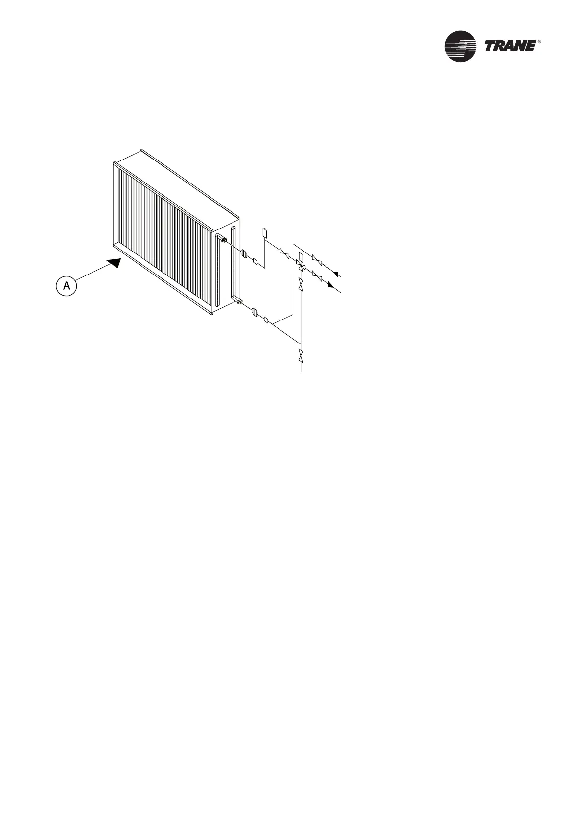
Figure 13 –
Water coil connections
1
1
6
6
4
5
2
2
3
A = Airflow
1 = Connections
2 = Gate valve
3 = Discharge gate valve
4 = Automatic air vent valve
5 = Automatic 3-way actuated valve
6 = Flexible joints
Referring to Figures 14-17, it is important to note that:
1. The cooling coil sections and the evaporative (or honeycomb) humidifier sections without recirculating pump
are equipped with a condensate drain pipe. (Item 1, Figure 14 (A, B)).
2. For evaporative humidifier sections equipped with are circulation pump, the drain pipe (used typically for
cleaning purposes, item 3, Figure 16 (A, B) needs to be connected to a shut off valve without siphon. There is
also an additional overflow pipe which needs to be connected to a siphon. (Item 1,Figure 15 (A, B)).
Figure 14 A indicates the siphon height for coil section located on negative pressure side.
Figure 14 B indicates the siphon height for coil section located on positive pressure side.
Figure 15 A indicates the siphon height for evaporative humidifier section located on negative pressure side.
Figure 15 B indicates the siphon height for evaporative humidifier section located on positive pressure side.
Figure 16 indicates the fresh water inlet for wasted water type or steam type humidifier sections. The freshwater
flow control in the section is ensured with a solenoid valve. It is recommended to fit a shut off valve to facilitate
the maintenance and a pressure regulator on the water entry for proper operation. The fresh water inlet must be
connected to the supply line with a flanges set.
Figure 15 indicates the fresh water inlet for evaporative humidifier sections equipped with a recirculating pump.
The fresh water flow is controlled with a floating valve located into the internal water tank. It is recommended to fit a
shutoff valve on the fresh water inlet to facilitate maintenance. The freshwater inlet must be connected to the supply
line with a flanges set.
The height of the U-trap varies upon the pressure inside the section and is given in mm of water column.
Installation