26
4 UNT-PRC002-GB
Technical Data
FWD 08 12 20 30 45
Power supply (V/Ph/Hz) 230/1/50
Capacities
Cooling capacity on water (1) (kW) 5,2 8,3 15 18,8 30,1
Heating capacity on water (2) (kW) 6,3 11,9 18,9 20,9 38,2
Fan motor (type) 2 x direct drive centrifugal
Fan power input (3) (kW) 0,23 0,46 0,65 1,04 1,51
Current amps (3) (A) 1,1 2,2 3,1 4,7 5,5
Start-up amps (A) 3,2 5,5 9,3 14,1 16,5
Air flow
minimum (m
3
/h) 490 980 1400 1800 2700
nominal (m
3
/h) 820 1650 2300 3000 4500
maximum (m
3
/h) 980 1970 2600 3600 5400
Main coil
Water entering/leaving connections (type) ISO R7 rotating female
(Dia) 3/4" 3/4" 1 1/2" 1 1/2" 1 1/2"
Electric heater (accessory for blower only)
Electric power supply (V/Ph/Hz) 230/1/50 230/1/50 or 400/3/50 400/3/50 400/3/50 400/3/50
Heating capacity (kW) 2/4 8 10 12 12
Hot water coil (accessory for blower only)
Heating capacity (4) (kW) 6,3 12 17,4 22,4 34,5
G2 filter (filter box accessory)
Quantity 2 2 2 2 2
Dimensions ( LxWxth) (mm) 386x221x8 486x271x8 586x321x8 586*421*8 586*621*8
G4 filter (filter box accessory)
Quantity - 2 2 2 2
Dimensions ( LxWxth) (mm) - 486x264x48 586x314x48 586*414*48 586*614*48
Condensate pump (accessory) (type) Centrifugal
Water flow - lift height (l/h - mm) 24 - 500
Not available for FWD30 and FWD45
Sound level (L/M/H speed)
Sound pressure level (5) (dB(A)) 36/40/43 38/41/44 46/50/53 47/52/57 47/52/58
Sound power level (5) (dB(A)) 46/50/53 48/51/54 56/60/63 57/62/67 57/62/68
Unit dimensions
Width x Depth (mm) 890 x 600 1090 x 710 1290 x 820 1290 x 970 1290 x 1090
Height (mm) 250 300 350 450 650
Shipped unit dimensions
Width x Depth (mm) 933 x 644 1133 x 754 1333 x 864 1333 x 1008 1333*1133
Height (mm) 260 310 360 460 660
Weight (kg) 32 46 61 76 118
Colour galvanised steel
Recommended fuse size
Unit alone (aM/gI) (A) 8/16 8/16 8/16 8/25 8/25
Unit with electric heater (gI) (A) 16 (2kW),25 (4kW) 40 (230V),3*16 (400V) 3*20 3*25 3*25
(1) Conditions: Water entering/leaving temperature: 7/12 °C, Air inlet temperature 27/19°C DB/WB - Nominal air flow
(2) Conditions: Water entering/leaving temperature: 50/45 °C, Air inlet temperature 20°C DB - Nominal air flow
(3) At high speed with nominal air flow.
(4) Water entering/leaving temperature 90/70 °C, air inlet temperature 20 °C DB, Nominal air flow.
(5) A rectangular glass wool duct 1m50 long is placed on the blower.The measurement is taken in the room containing the blower unit.
Heat exchanger operating limits:
FWD:
*water temperature: max 100° C
*absolute service pressure: min 1 bar/max 11 bars
Accessories - Hot water coil:
*water temperature: min. +2° C/max. 100° C
*absolute service pressure: min 1 bar/max 11 bars
AH-SVX03C-GB
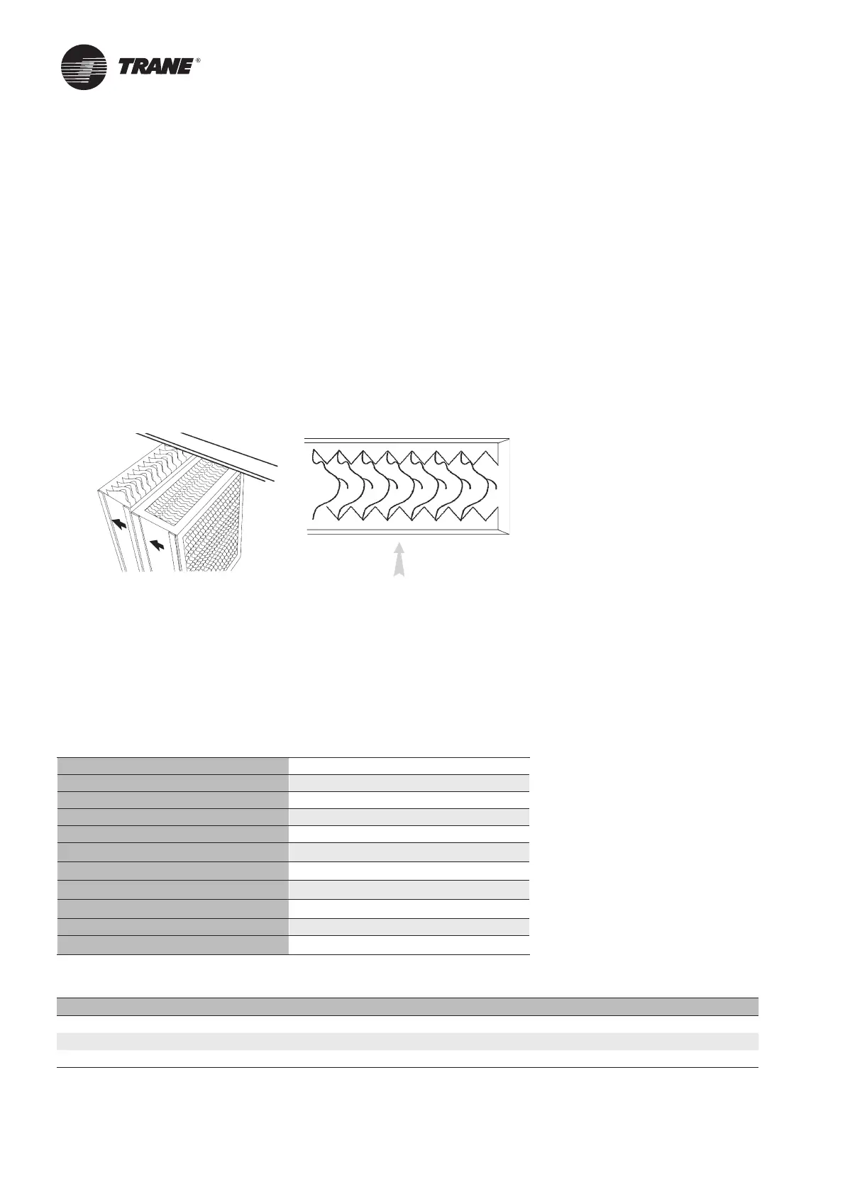
The regulating valve in the pressure side must be adjusted to the correct water quantity. The water purging volume
should be roughly equivalent to the amount of water evaporated from the system. On request we will advise you
in choosing the suitable volume. Check the correct setting with a manometer. The volume of water for sediment
flushing should be set by adjusting the flushing bleed off valve. Check the correct installation of humidifier and
moisture separator modules. The arrow must show in the direction of the airflow (see Figure 20).
Check the tightness of the seals of the air washer and humidifier units, ie between the modules. If necessary apply
additional sealant.
Water Quality for humidifiers and air washers.
The information hereunder which refers to the water treatment is given for reference only. Water quality is of prime
concern to ensure proper operation of humidifier and air washer.
The water hardness of the fresh water has to be measured before considering any water treatement.
In accordance with the inherent degree of hardness in the water and the operational priority of the air conditioning
installation, appropriate water treatment can then be selected.
Figure 20
CAUTION! : The use of improperly treated or untreated water in this equipment may result in scaling, erosion,
corrosion, algae or slime. The services of a qualified water treatment specialist should be engaged to determine what
treatment, if any, is required. The Trane warranty specifically excludes liability for corrosion or deterioration. Trane
assumes no responsibility for equipment damage or failure which results from the use of untreated or improperly
treated water or saline or brackish water.
Note: Honeycomb material made of cellulose may emit a certain smell during the first working hours. The is
absolutely normal and will disappear quickly.
To ensure a reasonable level of operational reliability, the quality of the supply water should be within the following
parameters (See tables 2 and 3).
Table 2
Appearance clear, colorless and free of sediment
pH Value 7 to 8.5
Conductivity max. 30 mS/m
Total Hardness max. 8.1
Carbonate hardness max. 3.5 mol/m3
Total salt content max. 250 g/m3
Chloride content 0 g/m3
Sulphate 0 g/m3
Manganese max. 0.01 g/m3
Agressive Carbonic Acid 0 g/m
KMnO4 usage max. 20 g/m3
Table 3 –
Conversion factors for grades of hardness
Grade of hardness ° F H. ° D H. ° GB H.
France 1° F H 1 0,562 0,702
Germany 1° D H 1,78 1 1,25
Great Britain 1° GB H 1,424 0,8 1
Commissioning procedure