AFDH-SVN01A-EN 55
Installation
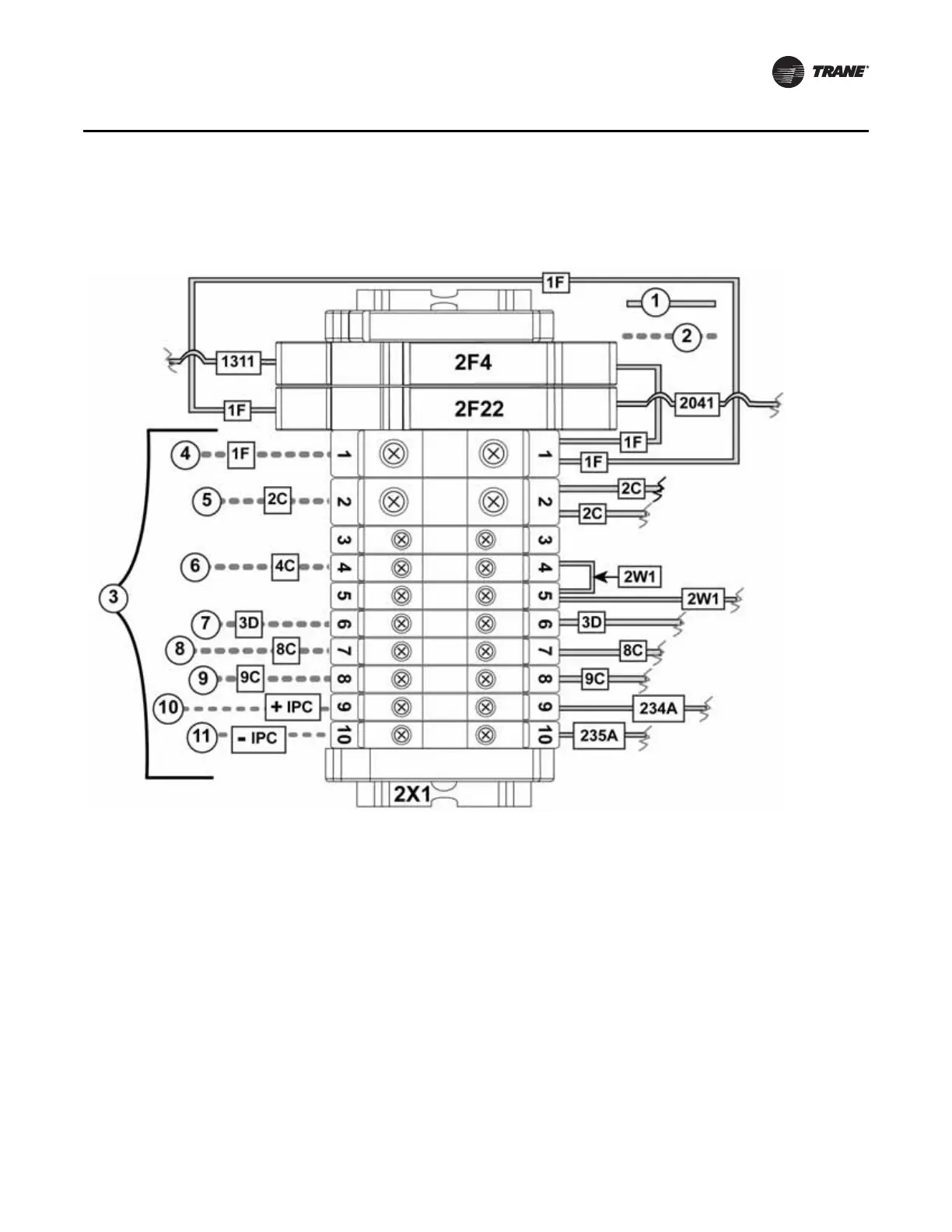
Control wiring connections (UCP2 model AFDH only)
1. Factory installed wiring
2. Field installed wiring
3. Note: actual wire designators may vary depending upon the specific model/version of chiller control
that the AFDH drive is being linked with. Please refer to the original chiller control wiring diagrams and
the wire descriptions listed in Figure Callouts 4 - 11 if an actual wire designator does not match the one
shown in this graphic
4. 115 VAC feed to chiller control panel
5. Neutral feed to chiller control panel
6. Normally Closed terminal(2) on HPC (High Pressure Cutout) switch (3S1)
7. 115 VAC feed from breaker 1CB1 in the chiller control panel
8. From 1TB1-7 (oil pump interlock 2K1)
9. From 1TB1-8 (oil pump interlock 2K1)
10 & 11. From IPC communication buss link
Important: Do not forget to install the condenser pressure transducer provided in the UCP2
Miscellaneous Hardware Package. The accurate pressure readings required by the
chiller controls to enable the most efficient operation of the chiller with the retrofitted
AFDH drive can only be effectively measured with a pressure transducer.
Figure 31. UCP2 wiring connections to 2X1 terminal strip in AFDH control box
 Loading...


