Installation
AFDH-SVN03H-EN 35
Harmonic Filter
Unit Description
Optionally, the AFDH may be ordered with a passive
harmonic filter. While the filter is passive, it adapts to
various loads in order to optimally reduce current
distortion (THID). The filter maintains a THID performance
of 8% MAX at 30% load and 5% MAX at full load. The filter
will also help to meet IEEE-519 Requirements (5% THID)
when used at lighter loads.
The amp rating of the ordered filter must be paired with
the drive. Filters are available in the following maximum
amp ratings: 320 A, 403 A, 482 A, 636 A.
About the Cabinet
The filter enclosure is designed to be mounted remotely
from the chiller. Refer to “Environmental Conditions and
Location,” p. 35 when selecting a location to mount the
filter.
Environmental Conditions and
Location
Important: Location of the harmonic filter is important
if proper performance and normal
operating life is to be expected. Therefore,
unless designed for special environments,
the controller should be installed in an area
where the following conditions exist:
• Verify that NEMA 1 enclosure is installed where it can
be kept clean and dry, away from oil, coolants, or other
airborne contaminants. The enclosure must be
installed in a non-corrosive location.
• The area chosen should allow the space required for
proper
air flow. Adequate clearance for air circulation
around the enclosure is a 6 inch (15.25 cm) minimum
clearance required wherever vents are located in the
cabinet.
• The area chosen should allow for service clearance in
front
of the enclosure. Three feet (0.91 m) is
recommended for door swing and working space;
more space may be required by local building codes or
for service equipment, such as hoists used for drive
replacement. Because codes and equipment may vary,
determine the amount of space required for each
specific installation.
• Do not install the harmonic filter over 1000 meters
(3300
feet) above sea level without derating output
power. For every 160 meters (528 feet) over 1000
meters (3300 feet) above sea level, derate the output
current 1 percent.
• IDEALLY, THE FILTER SHOULD BE INSTALLED AS
CLOSE
TO THE AFD AS POSSIBLE. RECOMMENDED
MAXIMUM CABLE DISTANCE BETWEEN THE FILTER
AND DRIVE IS 100 FEET.
• Line voltage is 480 Vac ±10%, 60 + 0.75 Hz, 3 phase
• Verify that the drive location will meet the
environmental conditions specified in Table 12, p. 35.
Installation Guidelines
Lift the filter into position on existing or new concrete pad.
Care should be used to prevent damage due to dropping
or jolting when moving the filter. A fork lift truck or similar
means of lifting and transporting may be used. Sling in a
manner that will equalize the load at the pickup points. Use
a spreader bar if the angle of the sling is less than 45°
relative to horizontal. Do not jolt while lifting.
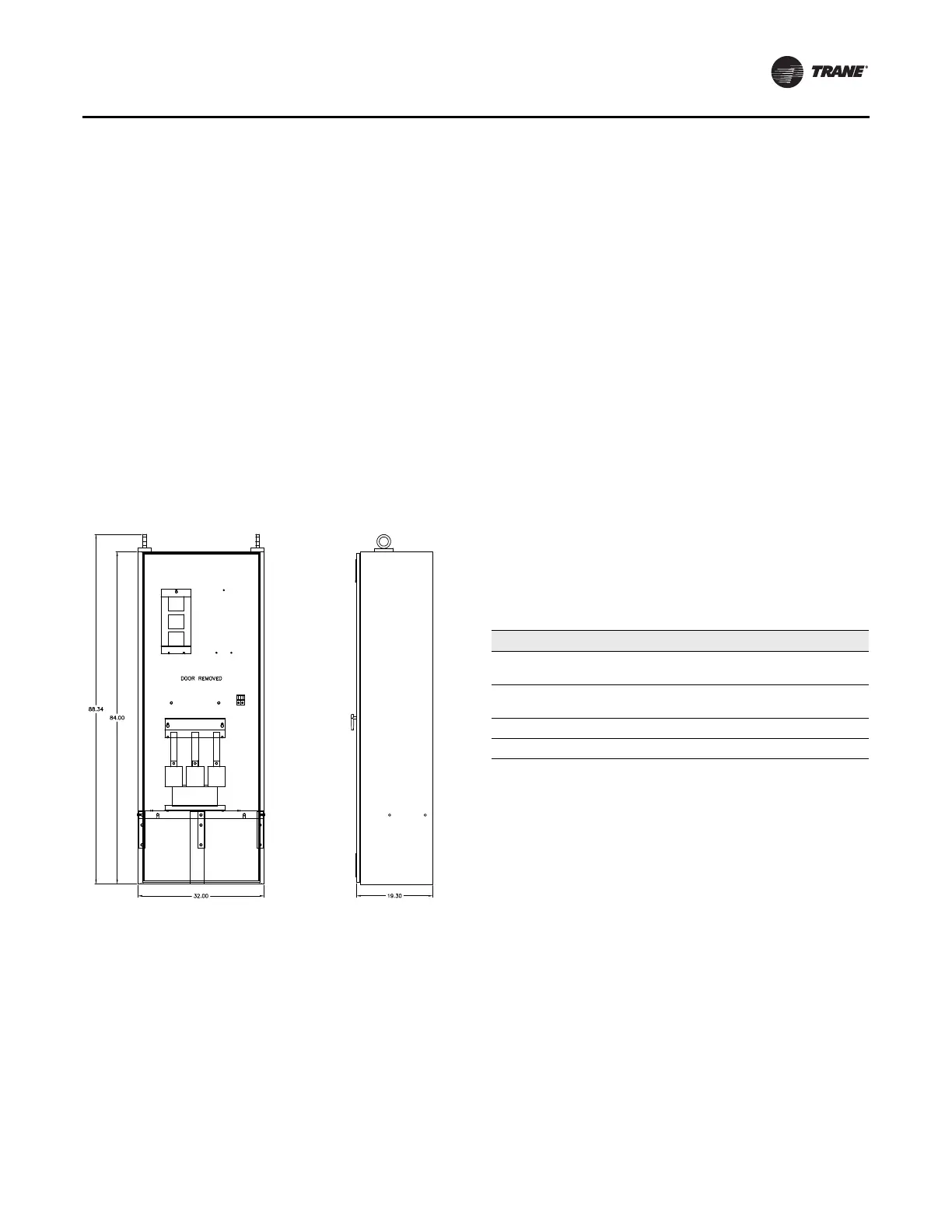
Figure 32. Filter enclosure
Table 12. Environmental conditions
Condition Specification
Operating Temperature (inside
NEMA 1 enclosure)
-40°C to + 50°C (-40° to 122°F)
Ambient Temperature (outside
NEMA 1 enclosure)
-40°C to + 40°C (-40°F to 104°F)
Storage Temperature (Ambient) -40°C to 70°C (40°F to 158°F)
Humidity 0% to 95% (non-condensing)
 Loading...


