40
CVHE-SVX02M-EN
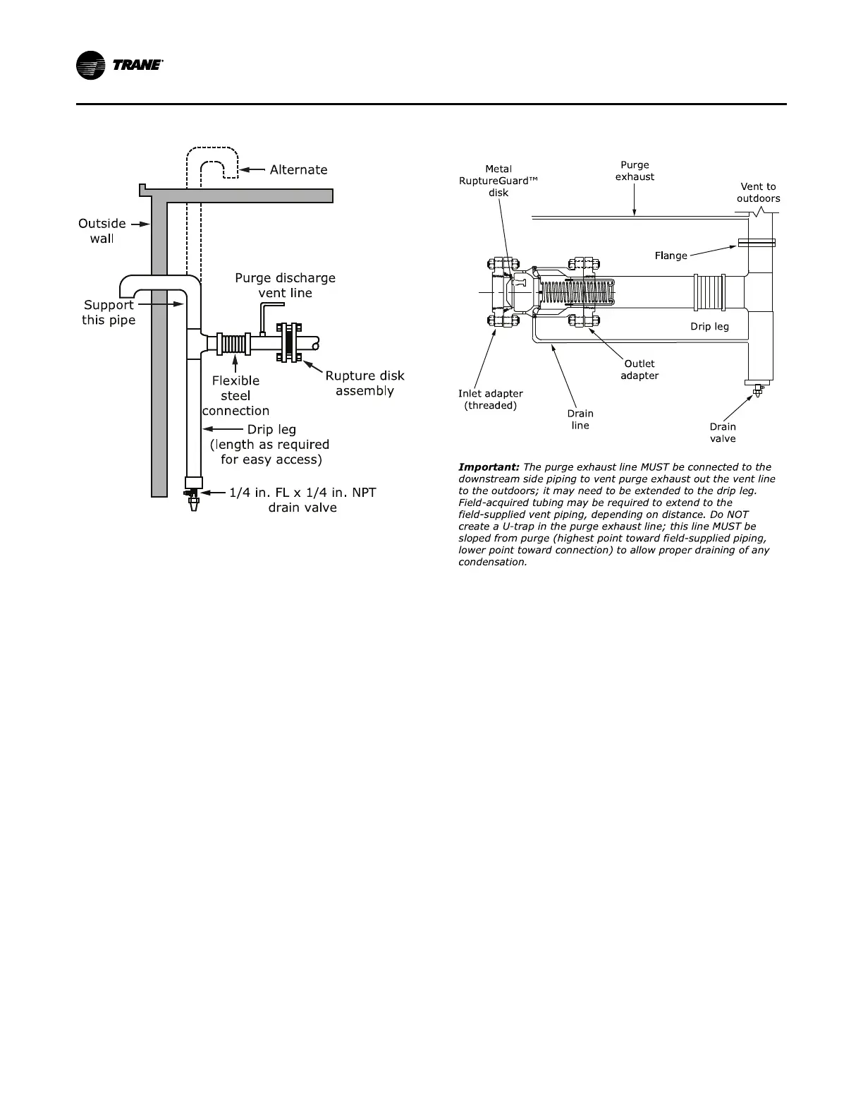
Figure 25. Arrangement for rupture disk relief piping
IImmppoorrttaanntt:: On the purge discharge vent line, the purge
exhaust connection point MUST be lower
than the purge height. Do NOT create a U-
trap; extend to drip leg if necessary to
avoid a trap.
NNootteess::
• If a RuptureGuard
™
is to be installed,
remove and discard the factory-installed
rupture disk; for more information, refer to
Installation, Operation, and Maintenance:
RuptureGuard Pressure Relief System
Option (CTV-SVX06*-EN).
• The rated flow capacity of the
RuptureGuard
™
disk/valve assembly is
based on having straight pipe extending
past the spring mechanism downstream of
the valve. Be sure there are no crosses (a
derate on the rated flow capacity for this
configuration is published in Engineering
Bulletin: RuptureGuard Selection Guide [E/
CTV-EB-10]), elbows, tees or any other
obstructions within the first 9 in. (228.6 mm)
of valve discharge. Refer to ASHRAE
Standard 15 for additional requirements on
piping rupture disk and relief valve vent
lines.
Figure 26. RuptureGuard™™ external vent line and
drip leg (not provided)
NNootteess::
• Use Loctite
®
242 or Loctite
®
277 on all
threaded joints on chillers charged with
refrigerant; use of other pipe thread sealants
is NOT recommended. Ensure all threaded
pipe joints are properly cleaned and
prepared before assembly. An alternative to
the use of Loctite
®
is to thread and weld the
inlet adapter to the pipe. Care must be taken
to ensure that the flange mating surface
remains flat. Do NOT weld on the Inlet
Adapter flange while connected to the
RuptureGuard
™
.
• The drip leg is required and must be drained
periodically for proper chiller purge
operation.
IImmppoorrttaanntt:: If a RuptureGuard
™
is to be installed, it
MUST be installed properly. Failure to
properly install RuptureGuard
™
will likely
result in a start-up delays and required
rework and expenses that result from a
failure to properly install RuptureGuard
™
will NOT be paid by Trane.
VVeenntt PPiippiinngg