CVHE-SVX02M-EN
39
NNOOTTIICCEE
PPrrooppeerr RReeffrriiggeerraanntt VVeenntt LLiinnee
TTeerrmmiinnaattiioonn!!
FFaaiilluurree ttoo pprrooppeerrllyy tteerrmmiinnaattee aa rreeffrriiggeerraanntt vveenntt
lliinnee ccoouulldd rreessuulltt iinn eeqquuiippmmeenntt ddaammaaggee..
IImmpprrooppeerrllyy tteerrmmiinnaattiinngg aa rreeffrriiggeerraanntt vveenntt lliinnee
ccoouulldd aallllooww rraaiinn ttoo eenntteerr tthhee lliinnee.. AAccccuummuullaatteedd
rraaiinnwwaatteerr ccoouulldd ccaauussee tthhee rreelliieeff ddeevviiccee ttoo
mmaallffuunnccttiioonn;; oorr,, iinn tthhee ccaassee ooff aa rruuppttuurree ddiisskk,, tthhee
rraaiinnwwaatteerr pprreessssuurree ccoouulldd ccaauussee tthhee ddiisskk ttoo rruuppttuurree,,
aalllloowwiinngg wwaatteerr ttoo eenntteerr tthhee cchhiilllleerr..
• Route the vent-line piping so that it discharges
outdoors in an area that will not spray refrigerant
on anyone. Position the vent-line discharge at least
15 ft (4.6 m) above grade level and at least 20 ft
(6.1 m) from any building opening. Provide a vent-
line termination that cannot be blocked by debris or
accumulate rainwater.
• Provide a drip leg on the vent line (refer to Figure
25, p. 40). Provide a standard 1/4-in. FL x 1/4-in.
NPT, capped refrigerant service valve to facilitate
liquid removal.
NNOOTTIICCEE
EEqquuiippmmeenntt DDaammaaggee!!
FFaaiilluurree ttoo ffoollllooww iinnssttrruuccttiioonnss bbeellooww ccoouulldd rreessuulltt iinn
eeqquuiippmmeenntt ddaammaaggee..
AAllll vveenntt lliinneess mmuusstt bbee eeqquuiippppeedd wwiitthh aa ddrriipp lleegg ooff
ssuuffffiicciieenntt vvoolluummee ttoo hhoolldd tthhee eexxppeecctteedd
aaccccuummuullaattiioonn ooff wwaatteerr aanndd//oorr rreeffrriiggeerraanntt.. TThhee ddrriipp
lleegg mmuusstt bbee ddrraaiinneedd ppeerriiooddiiccaallllyy ttoo aassssuurree tthhaatt iitt
ddooeess nnoott oovveerrffllooww aanndd aallllooww fflluuiidd ttoo ffllooww iinnttoo tthhee
hhoorriizzoonnttaall ppoorrttiioonn ooff tthhee vveenntt lliinnee.. TTrraannee aassssuummeess
nnoo rreessppoonnssiibbiilliittyy ffoorr eeqquuiippmmeenntt ddaammaaggee ccaauusseedd bbyy
iinnssuuffffiicciieenntt ddrraaiinnaaggee ooff ddrriipp lleegg..
• Consult local regulations and codes for any
additional relief line requirements and refer to
appropriate refrigerant handling guidelines. For R-
123 chillers, refer to Installation, Operation, and
Maintenance: R-123 Low-Pressure Refrigerant
Handling Guidelines Conservation and Safe
Handling of R-123 Refrigerant in Trane Chillers for
Service Technicians (CTV-SVX05*-EN). For R-514A
chillers, refer to Installation, Operation, and
Maintenance: R-514A Low-Pressure Refrigerant
Handling Guidelines Conservation and Safe
Handling of R-514A Refrigerant in Trane Chillers for
Service Technicians (CTV-SVX008*-EN).
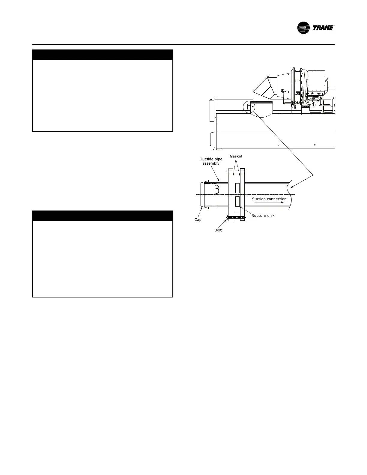
Figure 24. Rupture disk location and cross section of
rupture disk
NNoottee:: Pipe connection is 3 in. (76.2 mm) NPT, except
250E evaporator/250L condenser units with heat
recovery which have a 4 in. (101.6 mm) NPT pipe
connection.
VVeenntt PPiippiinngg